
1. Deployment Preparation #
Recommended deployment environment:
X86 sever
Linux Version: Ubuntu 18.04 LTS or later
Docker Version: 20 or late
| Device Number | CPU | Memory | Disk |
|---|---|---|---|
| 500 | 4U | 8G | 500GB |
| 1000 | 8U | 16G | 1000GB |
| 2000 | 8U | 16G | 1500GB |
| 5000 | 16U | 32G | 2000GB |
2. Deployment Steps #
- 1. Upload the controller package file to the target deployment environment and perform a one-click installation. Use the –i parameter to specify the controller IP address.
./controller_V1.0_R07.bin –i <ip_address>
Users can directly access the controller via this IP address.
Note :When upgrading from versions prior to R7 to versions post-R7 while retaining existing configurations, perform the installation without the –i parameter.
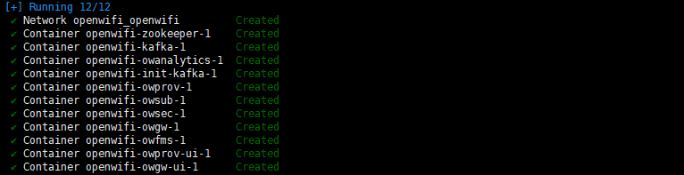
./controller_V1.0_R07.bin- 2. By default, the controller can be automatically started after the deployment is complete, and if you need to manually start the controller, you can run the following command, the default installation directory for the controller is /opt/controller/
cd /opt/controller/controller_V1.0_R07/wlan-cloud-ucentral-deploy/docker-compose/
docker-compose up -dDescription:
-d : runs the command in the background.
up : starts the controller.
down : stops the controller.
3. Controller Web Login and Logout #
The following browsers are not supported: Internet Explorer, Opera Mini and all versions of browsers that are no longer receiving updates.
Recommended browser: chrome version 114.0.5735.199 or later.
Controller address and default login information:
URL: https://openwifi.wlan.local/
Email: aster@asterfusion.com
Password: Asteria

4. Organization and Inventory Management #
The controller supports multi-organizational structures, allowing multiple venues to be divided under each organization for independent management. When the controller is deployed in a cloud environment, different organizations can be separately managed by different administrators, enabling parallel usage by multiple organizations and users.
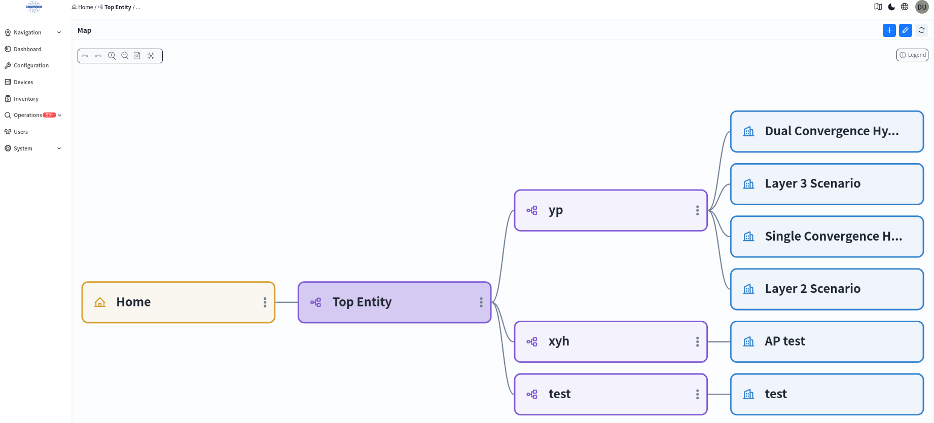
After logging into the controller, the system will default to the [Navigation] – [Map] page, as shown below. This page displays all organizations visible within the current user’s permissions and their subordinate venues in a structured view. System administrators can view the entire organization and venue structure under the controller, while ordinary administrators can only view content within their permissions.
On the Map page, administrators can manage existing organizations and venues or create new organizations or venues as needed. Double-click an organization or venue node switches to the device view under that area, enabling operations such as network device deployment, monitoring, and maintenance.
By default, the left-side navigation bar displays aggregated device information across all organizations within the user’s permissions. When a user enters a specific organization/venue via the [Map], the system focuses on that area and shows detailed information about all its devices, facilitating refined management.
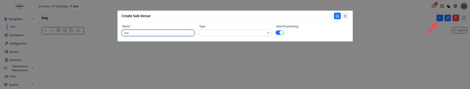
4.1 Create an Organization
click the [+] in the upper right corner to add an organization.
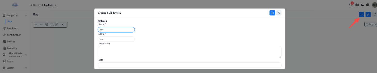
Double-click the created organization to go under the organization:
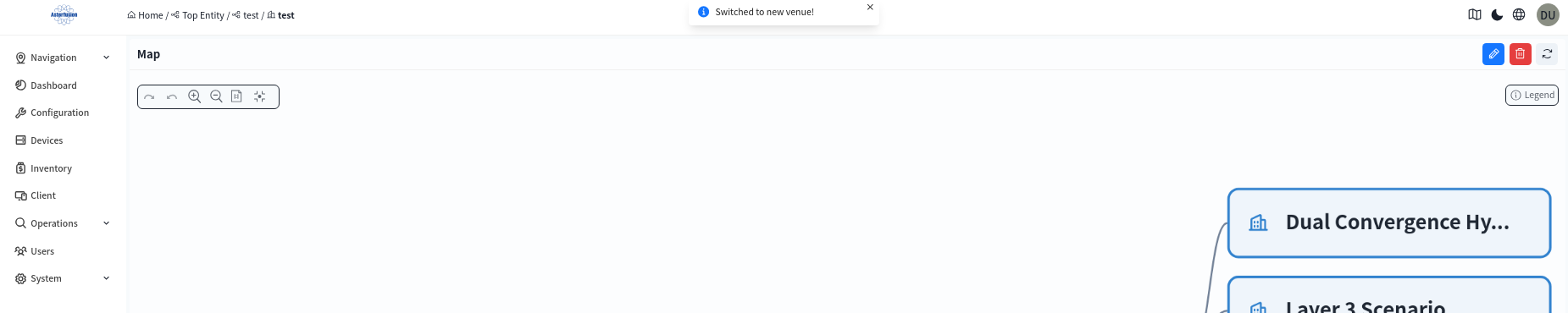
click the [+] to add a venue.
The venue is a collection where administrator can monitor, manage, and configure all network devices.
4.2 Adding Inventory
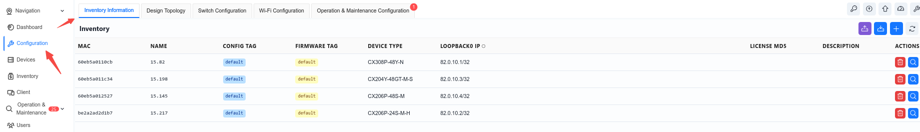
The administrator can add inventory devices to the organization/venue by creating or batch importing them under the venue. Up to this point, once the device is online, the controller will compare the MAC address of the online device, corresponding to the device in the inventory, and assign it to the specific organization/venue.
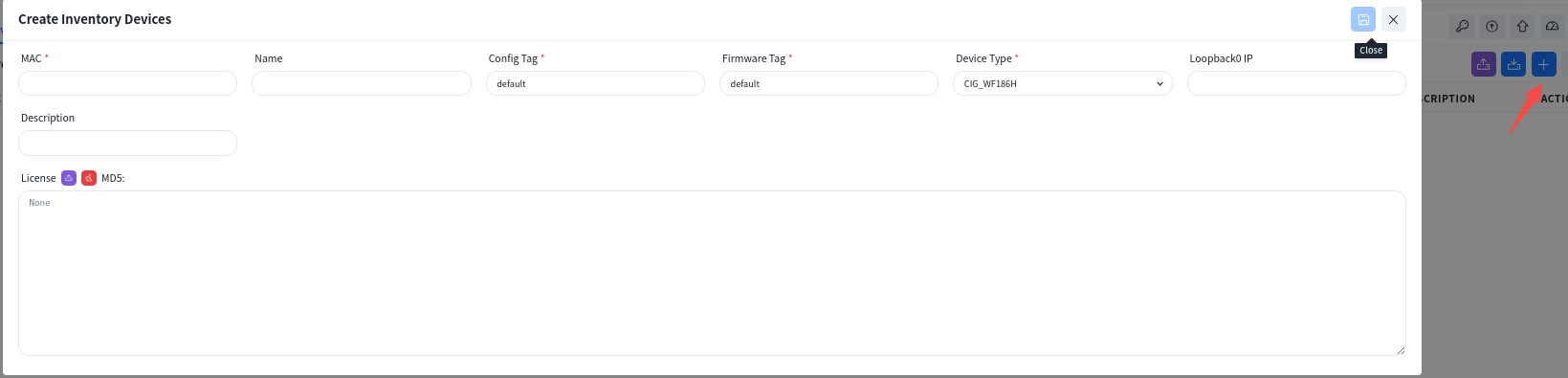
- Add devices one by one
- Use the excel file to upload devices
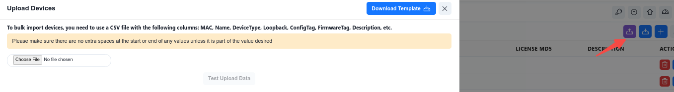
Click [Download Template] and fill in the device information to be added to the inventory according to the template specifications.

Required Fields:
- MAC: The MAC address of the device, usually labeled on the device.
- Device Type: The model of the device.
- Firmware Tag: When upgrading device firmware, you can filter devices to be upgraded by firmware tag type. By default, the tag value is “default”.
- Config Tag: After connecting to the controller, the AP will automatically pull the configuration file corresponding to this tag. By default, the tag value is “default”.
Optional Fields:
- Name: The hostname of the device.
- Loopback0 IP: The Loopback address of the device, which serves as the in-band management address for all Layer 3 devices.
- Description: The information of the device.
- License: The AP License file content. For batch import, you can fill in the content of the JSON-formatted License file in Excel, or add all devices to the inventory first and then import Licenses in batch.
5. Device Connect to Controller #
5.1 Connect to Controller by DHCP
All Asterfusion devices can act as DHCP clients. Under the factory default configuration, they will actively send DHCP request to obtain the management IP address and the controller IP address.
To ensure that devices can obtain the controller IP through DHCP requests, the DHCP server must be capable of responding to the option 138 field. The following is a configuration example for the ISC-DHCP server:
subnet 192.168.1.0 netmask 255.255.255.0 {
  range 192.168.1.100 192.168.1.200;
  option routers 192.168.1.1;
  option subnet-mask 255.255.255.0;
option capwap-ac-v4 "192.168.10.254"; Description:192.168.10.254 is the IP address of the controller.
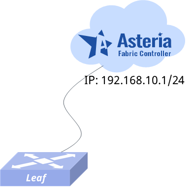
5.2 Connect to Controller by Command Line
If the DHCP server does not exist in the network, or the DHCP server cannot be configured with the controller address, the user can use the command ucentral-client server <A.B.C.D> to configure the IP address of the controller on the switch so that the device can connect to the controller.
If the device uses out-of-band management and the management port belongs to VRF mgmt, users need to specify the VRF parameter when designating the management address, for example: ucentral-client server <A.B.C.D> vrf mgmt.
The following is a sample configuration for switch:
sonic# config
sonic(config)# ucentral-client enable
sonic(config)# ucentral-client server 192.168.10.1
sonic(config)# interface ethernet 49
sonic(config-if-49) ip address 192.168.10.20/24
6. Business Configuration #
To simplify the configuration of common typical network setups, the controller has three built-in scenarios: Large/Mid-Scale Campus, Traditional L2 Network, and Small/Mid-Scale Campus. Administrators can select any network setup according to the network scale to complete topology planning. After all devices in the planned topology are online and connected to the controller, the ACC will automatically detect and identify the connection status between devices to generate a real network topology. Administrators can check whether the topology is correct, and after confirming it is error-free, deploy the configuration to the devices to complete network configuration and deployment. After entering the specific venue, the administrator clicks the [Configuration] – [Design Topology] button to select the specific scenario to be used.
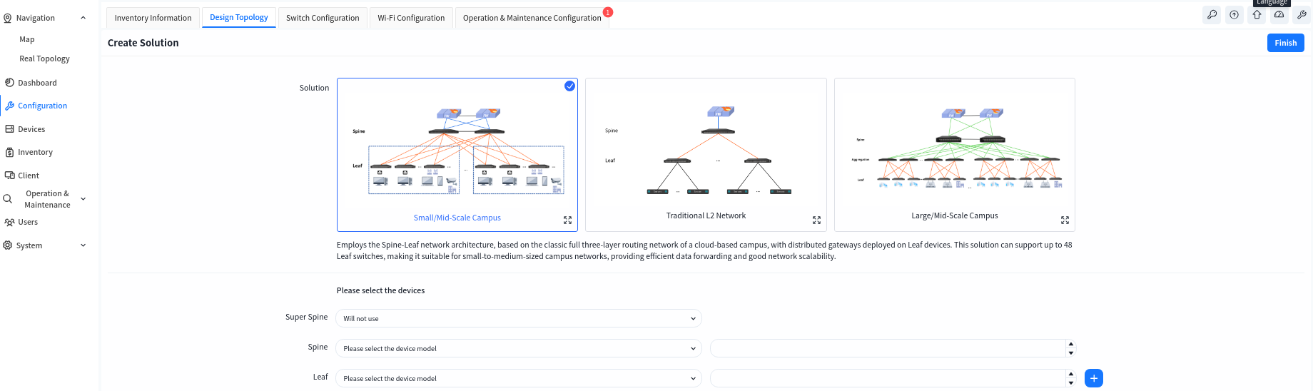
- Small/Mid-Scale Campus
This is a full L3 network solution with a two-tier Spine-Leaf architecture, for example, using the CX308 series as the Spine devices and the CX204Y-48GT series as the Leaf devices: each Spine device can provide up to 48 interfaces to connect with Leaf devices, and each Leaf device offers 48 access interfaces. Thus, the network can support up to 48 x 48 = 2304 access interfaces. This scenario is suitable for smaller scale network.
- Large/Mid-Scale Campus
This is a full L3 network solution with a three-tier Spine-Aggregation-Leaf architecture, for example, using the CX308 series as Spine devices, the CX206P-24S series as Aggregation devices, and the CX204Y-48GT series as Leaf devices: each Spine device can provide up to 48 interfaces to connect with Aggregation devices, each Aggregation device can provide up to 24 interfaces to connect with Leaf devices, and each Leaf device offers 48 access interfaces. Thus, the network can support up to 48 × 24 × 48 = 55,296 access interfaces. This scenario is suitable for larger scale network.
- Traditional L2 Network
Traditional L2 network solution, Spine-Leaf L2 architecture, Leaf for pure L2 access, gateway deployed on Spine device.
6.1 Small/Mid-Scale Network Deployment
6.1.1 Design Topology
Select the Small/Mid-Scale Campus network scenario, fill in the models and quantities of Spine and Leaf devices, then click [Save] to finish the pre-planning of the network topology. The controller will generate a recommended network topology based on the pre-planned typical network architecture.
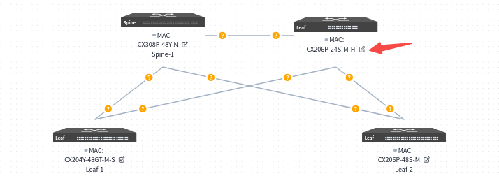
Users can click the [Edit] button on the device side, select devices from the inventory to be applied to the current topology in the slide-out panel on the right, and then choose interconnection interfaces.
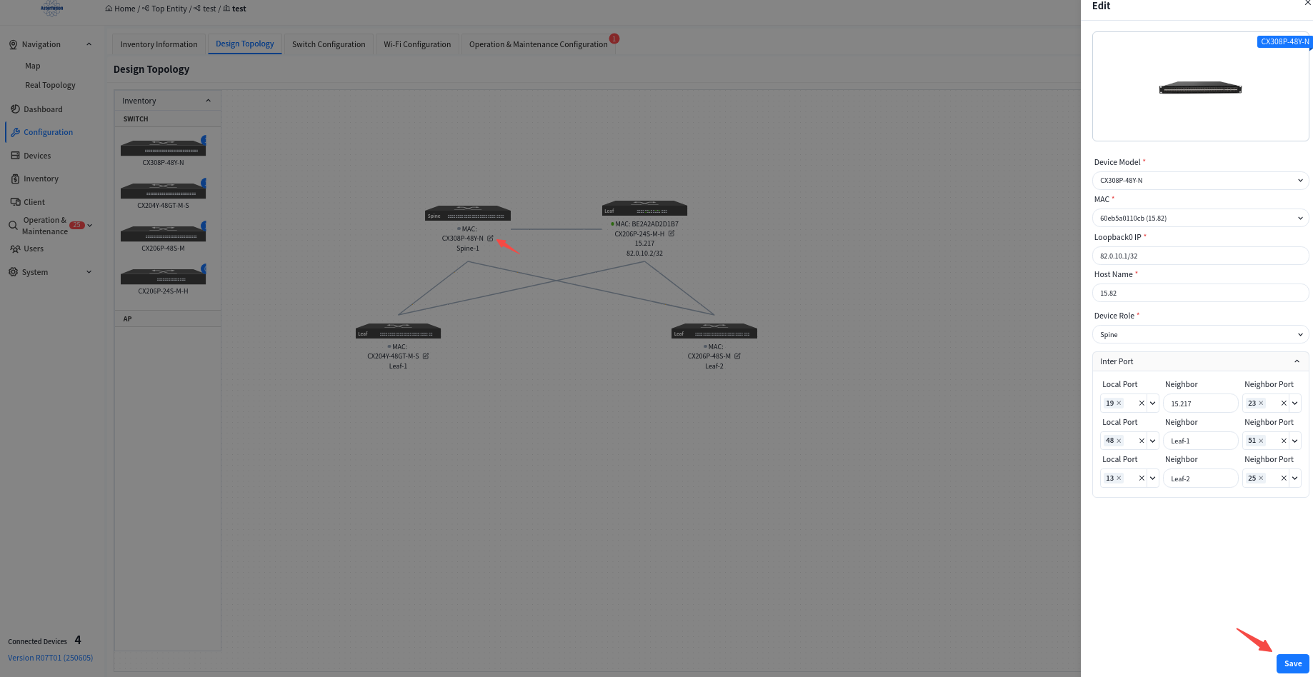
- MAC: Uniquely select a device via its MAC address.
- Loopback IP: Configure the IP address for the device’s Loopback0 interface, which will be used for in-band management of the device.
- hostname: Configure the hostname of the device.
- Device role: Assign the device role as Spine or Leaf.
- Interconnection Interfaces:
- Local Interface: The interface on the current device.
- Neighbor: Select the peer device connected to the local interface.
- Neighbor Port: The interface on the peer device interconnected with the current device’s local interface.
Once you have finished editing the topology, click the [Save] button in the upper right corner to save your edits to the topology.
Click [basic network] to enter the Basic Network Configuration interface to configure the basic network that carries the service network, including the routing protocols between Leaf and Spine, and between Spine and up-link devices. Besides information such as IP addresses that must be specified by the user, the controller will dynamically generate basic configurations based on the network topology that do not require the user’s attention.
6.1.2 Basic Network
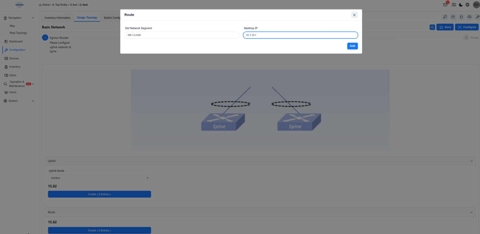
6.1.2.1 Egress Route
Configuring Spine device up-link interface information.
Configure the IP address of the Spine device uplink interface and static routing information on the Spine device.
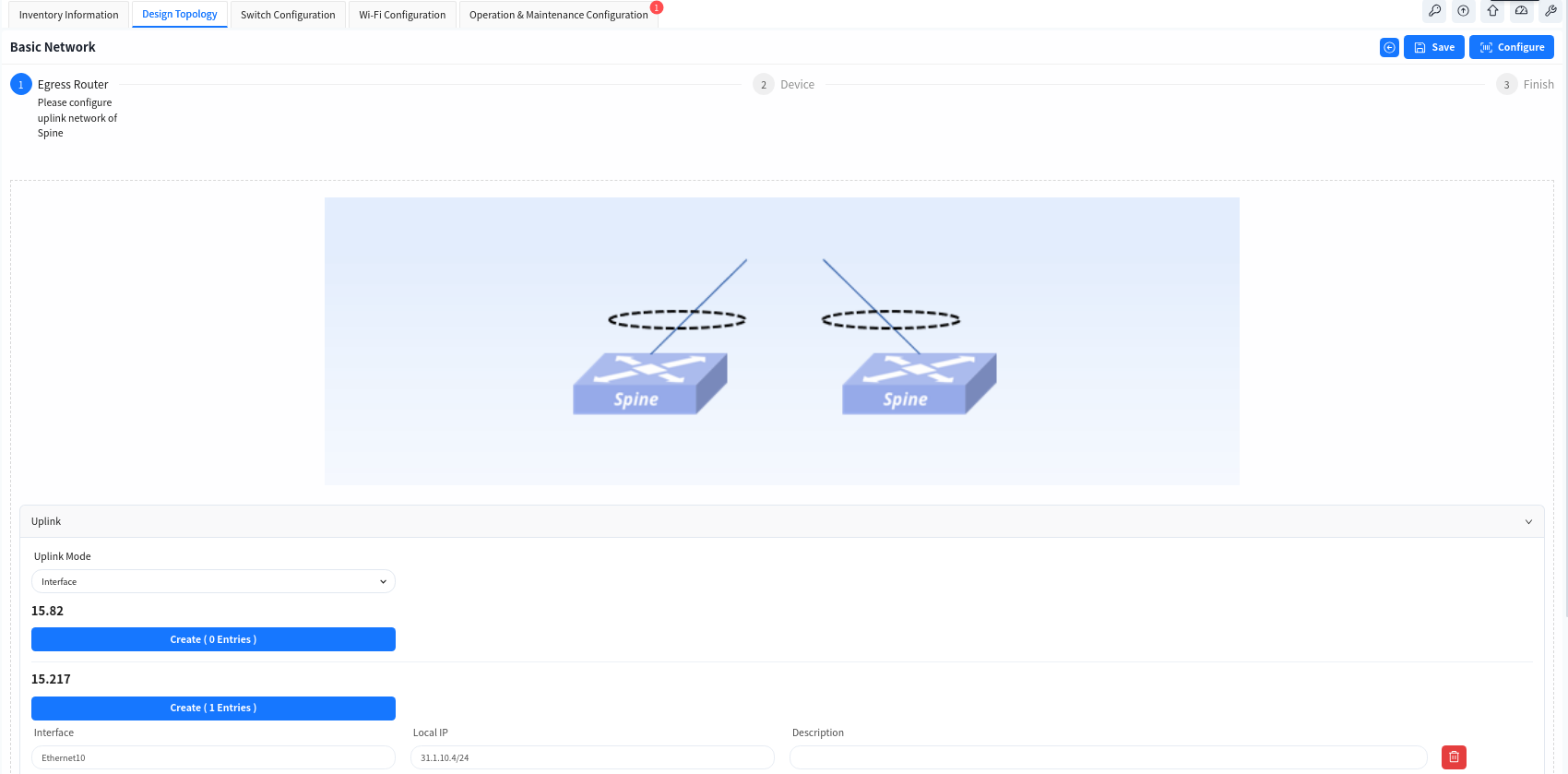
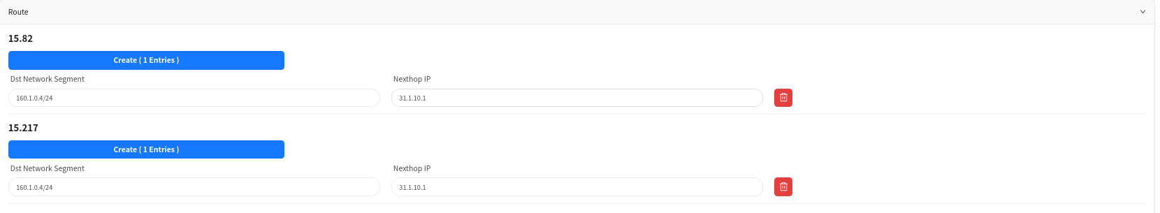
- If the Spine and the core device do not use static route but use dynamic route, user can click [Advance] button to configure it.
- [BGP Enable] Enable the BGP function of Spine device and configure the AS number and IP address information of the up-link device, so that Spine can establish BGP neighbor relationship with the up-link device.
- [OSPF Enable] Enable OSPF on Spine devices, configure the OSPF domain ID and establishment method, so that Spine and up-link devices can establish neighbor relationships via OSPF to synchronize routes.
- [Route Aggregation Enable] When the Spine devices enable the BGP function, the routing information of the terminal will be synchronized with the up-link device in form of aggregated routes.
- [HA] When enabled, the two Spine devices will provide a cross-device LAG interface to the up-link device through the MC-LAG function.
6.1.2.2 Device Management
Configure device management related information:
- TimeZone: Configure the system time zone.
- NTP: Configure NTP Server.
- SNMP: Configure SNMP community.
- Syslog: Configure syslog server IP address.
- TACACS+: Configure TACACS server IP address.
- Device ACL: Configure ACL rules restricting SSH, SNMP, TELNET connections to device.
6.1.3 Wired Service Configuration
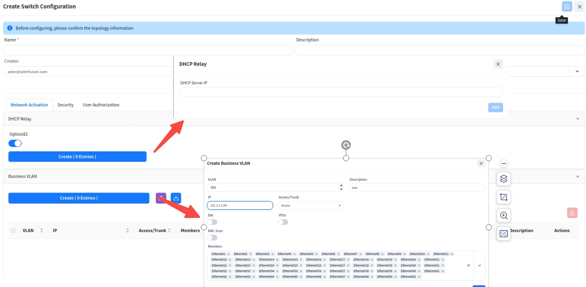
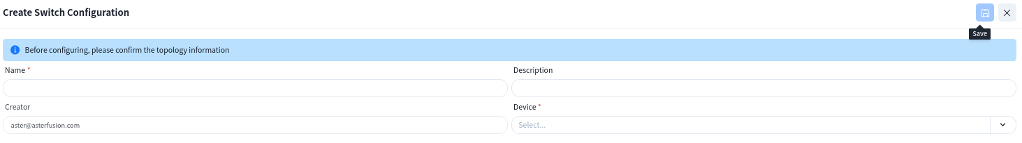
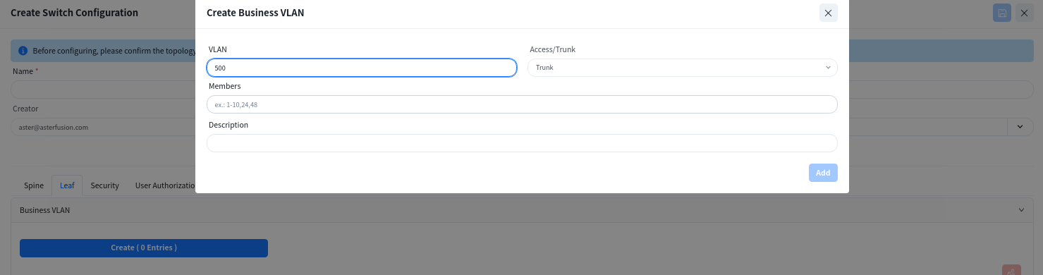
Click [Switch Configure] to enter the wired service management interface, where you can configure corresponding service VLANs and IP gateways on switches for wired and wireless users, and specify the IP address of the DHCP server. Multiple service VLANs can be added to handle different service requirements.
6.1.3.1 Service Activation
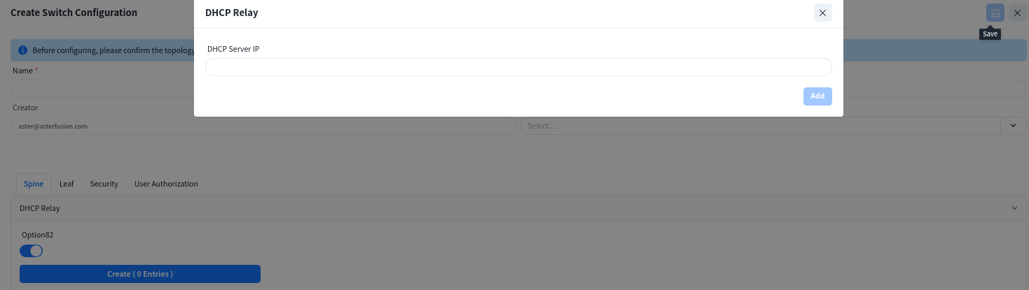
- [DHCP Relay]: Configure the DHCP server IP address. When the DHCP server does not support recognizing the option82 field, the option82 option needs to be disabled.
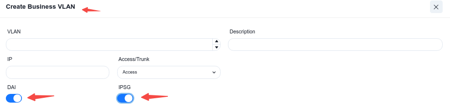
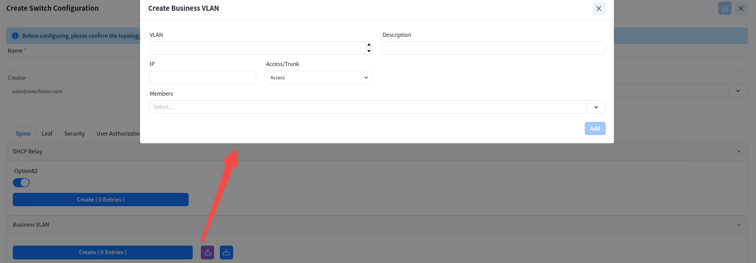
- [VLAN]: Create service VLANs. Note that in addition to basic service VLANs, a management VLAN for user APs to connect to the controller must also be created.
- [IP]: Configure an address as the gateway for the service VLAN.
- [Access/Trunk]: Select the mode according to whether the interface transmits/receives packets with VLAN tags.
- Access: Accepts packets without VLAN tag, typically configured for the AP management VLAN.
- Trunk: Accepts packets with VLAN tag, typically configured for service VLANs.
- [Member Interfaces]: Click the drop-down arrow to select the member interfaces of the VLAN.
6.1.3.2 Network Security Configuration [Optional]
- DAI/IPSG
The controller enables the DHCP Snooping function by default to effectively prevent DHCP Server impersonation attacks, ensuring DHCP clients obtain IP addresses from legitimate DHCP servers. Administrators do not need to manage trusted/untrusted interfaces on different devices-the controller automatically generates configurations based on topology information.
Administrators can enable ARP inspection (DAI) and IP source guard (IPSG) based on network security requirements. These functions validate host legitimacy using global DHCP Snooping entries to prevent malicious hosts from forging legitimate identities or attacking the network via self-assigned IP addresses, thus avoiding potential IP conflicts.
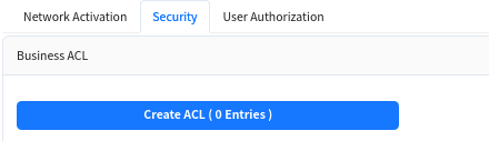
- Access Control List (ACL)
Administrators can further enhance network security by configuring device management ACLs and service ACLs to set blacklists/whitelists for user internet traffic.
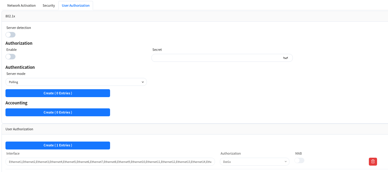
6.1.3.3 User Access Authentication Configuration [Optional]
In enterprise networks or public places with high security requirements, enable 802.1x-based user authentication. This ensures only authenticated users and devices can access network resources, enhancing security. Through the graphical interface, administrators can define and apply authentication policies, including specifying ports for 802.1x authentication and setting different authentication rules.
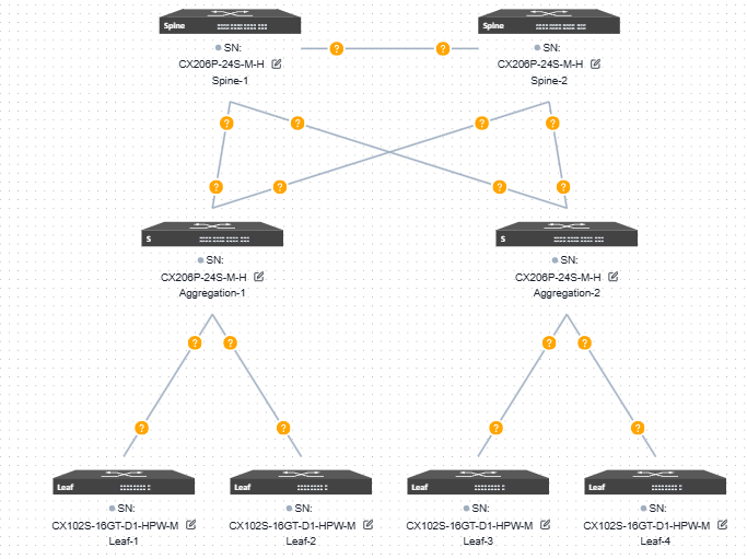
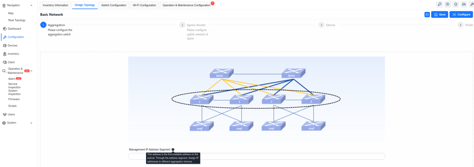
6.2 Large/Mid-scale Network Deployment
The Large/Mid-Scale Campus network adopts the Spine-Aggregation-Leaf three-level structure, and extends the number of accessible Leaf devices through Aggregation to further extend the number of access ports.
6.2.1 Design Topology
The device selection and topology editing are the same as the Small/Mid-scale campus networks. The topology overview is shown below:
6.2.2 Basic Network
6.2.2.1 Aggregation
Configure the in-band management network for aggregation devices. Typically. the Spine and Leaf devices are Layer 3 devices. in-band management can use the Loopback0 address. while the aggregation device is a Layer 2 device for which you need to configure the management VLAN and IP.
Controller can assign an in-band management address to each aggregation device based on the address segments that are entered by the user.
6.2.2.2 Egress Route
The configuration of this part is consistent with the Egress route of [Small/Mid-Scale Network Deployment], please refer to the previous section to complete the configuration.
6.2.2.3 Device Management
The configuration of this part is consistent with the Egress route of [Small/Mid-Scale Network Deployment], please refer to the previous section to complete the configuration.
6.2.3 Wired Service Configuration
The configuration of this part is consistent with the Egress route of [Small/Mid-Scale Network Deployment], please refer to the previous section to complete the configuration.
6.3 Traditional L2 Network Deployment
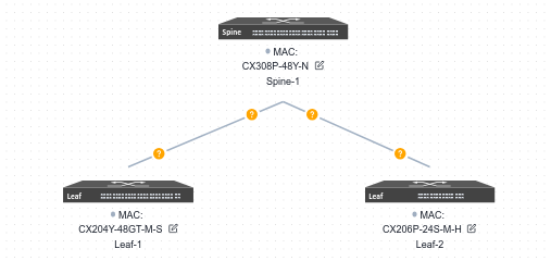
6.3.1 Design Topology
Device selection and topology editing is the same as for the Small/Mid-Scale Campus network. The topology is summarized as shown below:
6.3.2 Basic Network
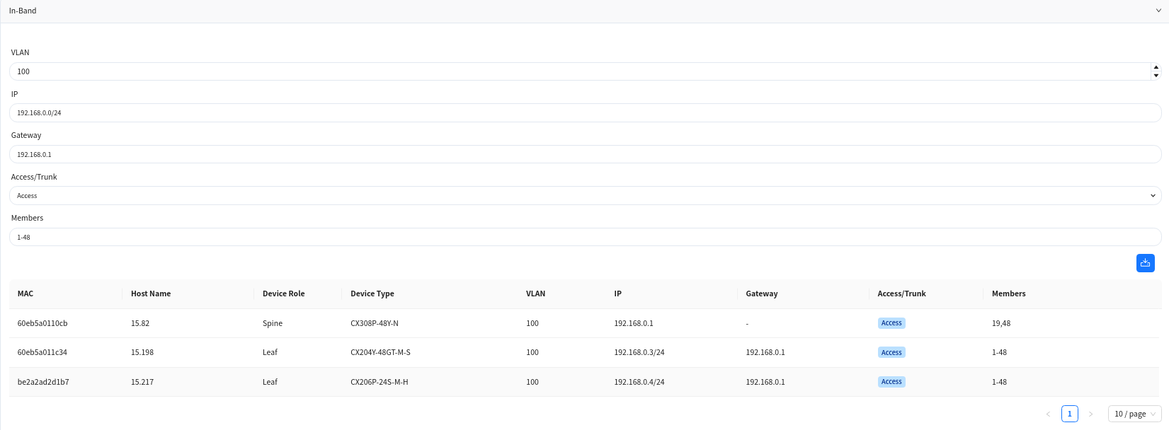
6.3.2.1 In-Band Management
In the traditional Layer 2 network scenario, the in-band management method for Leaf devices is as follows: create a VLAN interface as the in-band management interface to connect to the controller. On the current page, administrator can specify a VLAN ID as the in-band management VLAN, configure the address segment of the management IP and the gateway address for in-band management (this gateway address will be configured on the Spine device), and select the member interfaces of the VLAN and the mode (trunk/access) when joining the VLAN.
The controller will allocate a management IP address from the specified address segment for each Leaf switch and present the allocation results in the table below:
6.3.2.2 Egress Route
Select the interface ID of the Spine device’s up-link interface and configure the IP address.
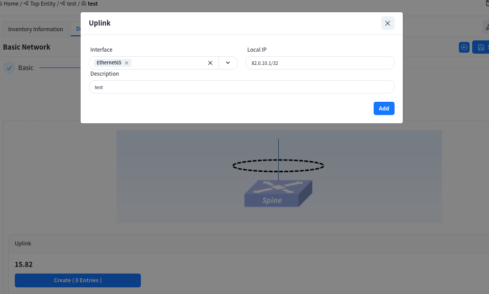
In the traditional L2 scenario, Spine devices only support connecting to external network by configuring static routes. To ensure normal network operation, it is generally necessary to configure a default route.
6.3.2.3 Device Management
The configuration of this part is consistent with the Egress route of [Small/Mid-Scale Network Deployment], please refer to the previous section to complete the configuration.
6.3.3 Wired Service Configuration
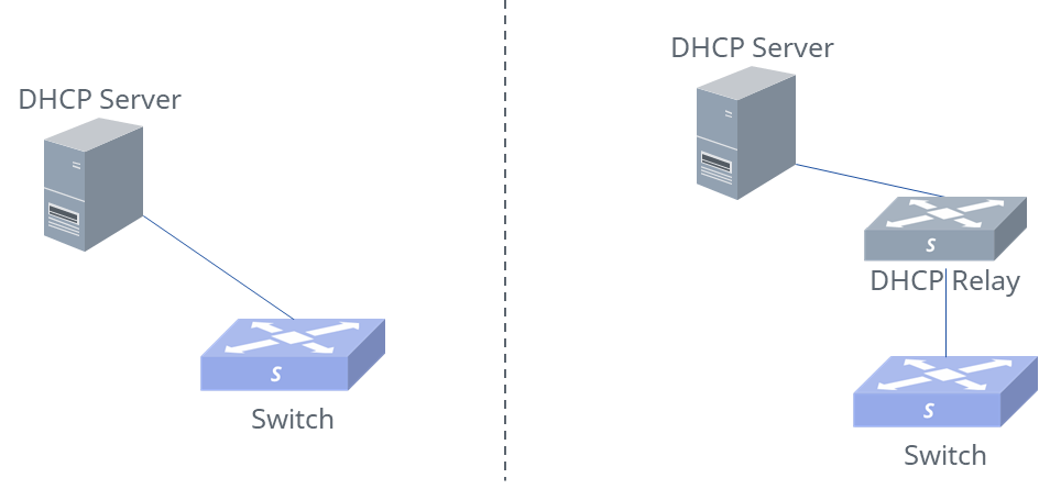
Unlike full L3 networks, the service network in traditional L2 networks is deployed on Spine devices. Therefore, when selecting devices, Spine-type devices must also be added.
6.3.3.1 Spine
In addition to serving as a service gateway, DHCP relay is enabled on Spine devices, allowing broadcast DHCP requests from APs and terminals to be converted into unicast packets via DHCP relay and sent to the DHCP server.
Create service VLAN:
- [DHCP Relay]: Configure the IP address of the DHCP server. When the DHCP server does not support recognizing the option82 field, the option82 option needs to be disabled.
- [VLAN]: Create service VLANs. Note that in addition to basic service VLANs, a management VLAN for user APs to connect to the controller must also be created.
- [IP]: Configure an address as the gateway for the service VLAN.
- [Access/Trunk]: Select the mode according to whether the interface transmits/receives packets with VLAN tags.
- Access: Accepts packets without VLAN tags, typically configured for the AP management VLAN.
- Trunk: Accepts packets with VLAN tags, typically configured for service VLANs
- [Member Interfaces]: Click the drop-down arrow to select the member interfaces of the VLAN on the Spine device, usually all interfaces connected to the Leaf switch.
6.3.3.2 Leaf
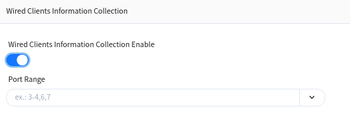
The Leaf switch is purely configured for Layer 2. On this interface, only the VLAN ID and member interfaces need to be specified, and all other configurations are generated by the controller.
Wired Terminal Information Collection Enable
Enabling this function on an interface will report terminal information under the interface to the controller.
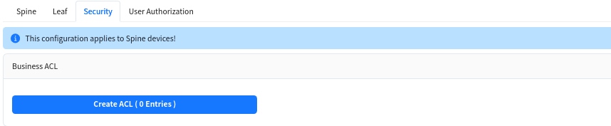
6.3.3.3 security [optional]
Create Service ACLs to configure access control lists between services in different network segments.
Note: This configuration takes effect on Spine devices, and VLAN isolation is applied between Leaf devices.
6.3.3.4 User Access Authentication Configuration [Optional]
The configuration of this part is consistent with the Egress route of [Small/Mid-Scale Network Deployment], please refer to the previous section to complete the configuration.
6.4 Wireless Service Configuration
Click [Wireless Configuration] – [+] – [Create Configuration] to configure the necessary basic information for the wireless AP, e.g. SSID settings, security policy. The controller can automatically generate the corresponding configuration script based on the administrator’s input.
The controller supports the configuration of different wireless service configurations, and after the AP goes online, it will determine which configuration should be issued to the AP based on the [CONFIG TAG] attributes of the configuration.
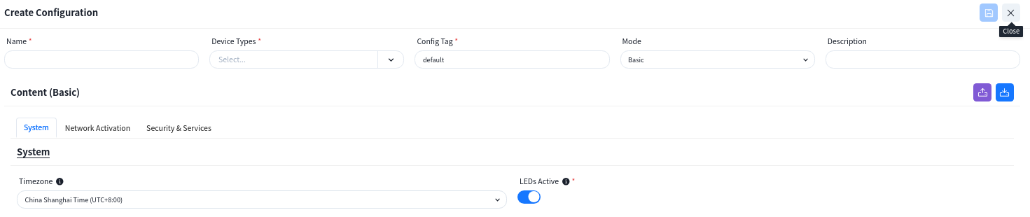
6.4.1 SSID
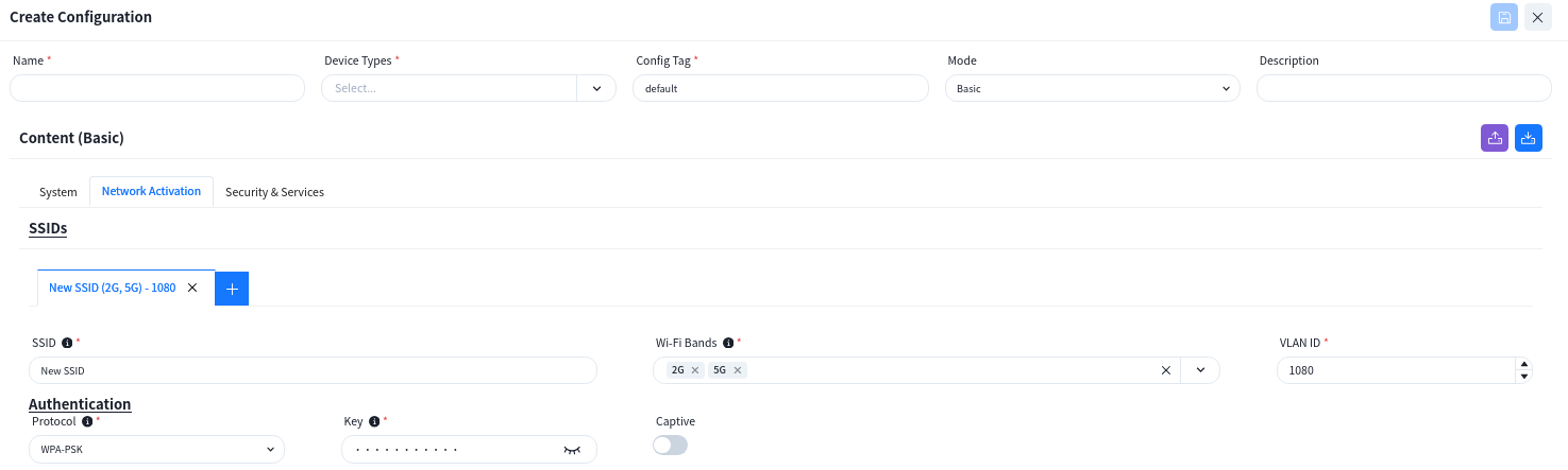
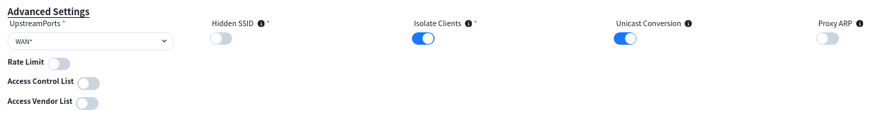
If there is a specific application scenario, the administrator can also customize the default configuration of the AP in the [advanced settings].
6.4.2 LAN
When the AP is one that has an extended wired interface and is capable of accessing terminals by wired means, such as a panel AP, the user can configure the access method for wired terminals through the configuration in LANs.
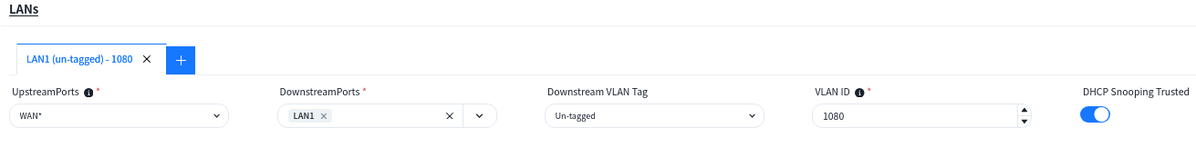
- up-link Ports: Specify the up-link interfaces for wired terminal to access the network through AP, usually it is the interface for AP to connect to the switch, and keep the same with [up-linkPort] in [SSID] – [Advanced] Settings, the default is: WAN*.
- down-link Ports: Interfaces for wired terminal access.
- down-link VLAN Tag: Whether the wired terminal carries VLAN Tag.
- VLAN ID:The AP receives messages from wired terminals that add this VLAN TAG to identify.
- DHCP Snooping Trusted: DHCP Snooping Trusted interface, if the wired terminal needs to obtain IP address through DHCP service, this switch needs to be on.
6.4.3 Wireless RF Configure
When the AP is online and connected to the controller, according to the actual deployment environment, if you need to adjust the wireless RF related configuration of the AP, you can configure it in the [Radio Configuration] page.

6.5 Configuration Release
6.5.1.1 Switch
Devices in the factory state, both management and service ports, with a status of Up will initiate a DHCP request to ask the DHCP server to provide a temporary management IP address and the controller IP address on the cloud to connect to the controller for configuration information.
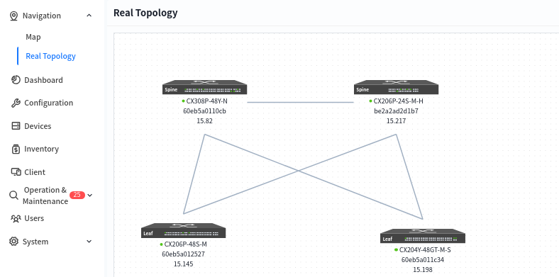
After all devices have finished going online, click [real topology] to confirm that the topology recognized by the controller based on the online devices is consistent with the design topology. After confirming that there is no error, follow the steps below to issue the configuration:
1.Enter the specified venue to be configured from the [Map] interface, and click [Design Topology] – [Basic Network] – [Configure] to issue the basic configuration for all devices.
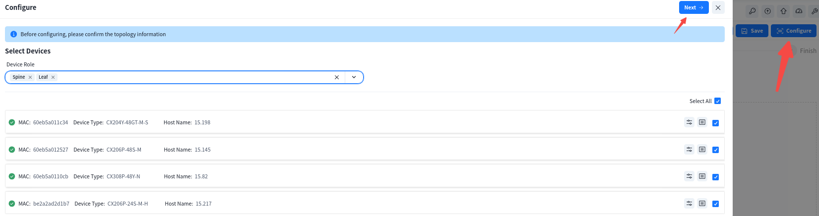
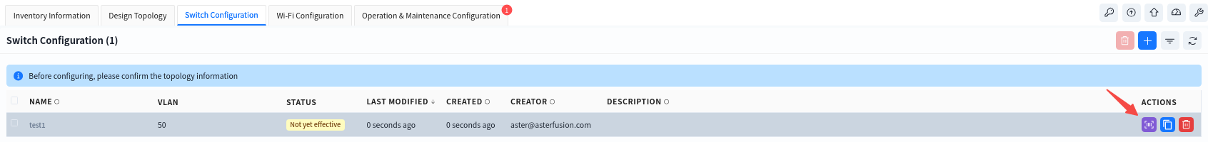
2. Click [switch configuration] – [configure] to issue a service configuration for the device.
6.5.1.2 AP
The AP does not need to manually issue the configuration. After the configuration of the device is issued and takes effect, the PoE power supply function of the switch is turned on, and the AP can power on and work. When the AP connects to the controller with the information obtained through the DHCP service, the controller will automatically send the configuration to the corresponding AP based on the comparison between the TAG identification stored in the AP inventory and the TAG identification in the planning configuration.
7 Firmware management #
7.1 Firmware
Firmware management is an important feature of the controller for managing version image files and patch files for network devices. Users can upload local images to the controller for easy deployment of new software versions throughout the network, or update network devices directly with the uploaded firmware.
Administrators can upload local version images to the controller and record basic information about software versions.
7.1.1 Firmware Upload
The administrator can upload the local version image to the controller and record the basic information of the software version.
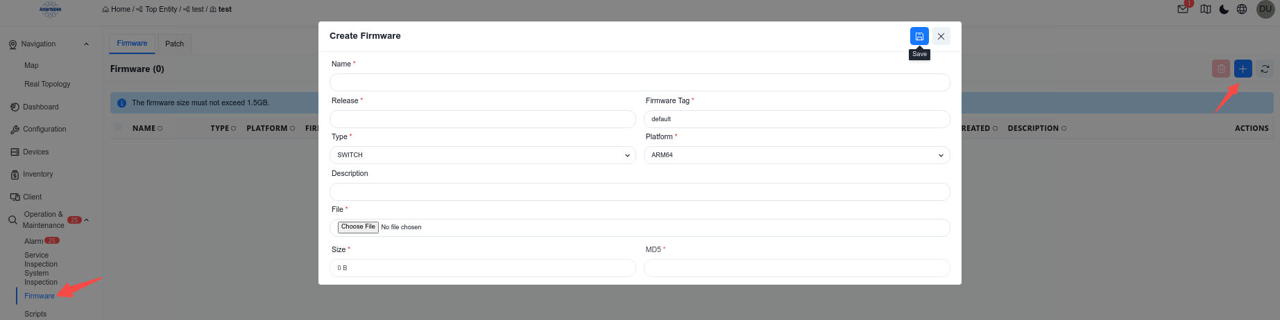
Operation steps:
1.Go to [Operation&Maintenance] – [Firmware] – [Firmware].
2.Click [+] to upload the version image to the controller.|
3.Use [Type] to distinguish whether the firmware applies to the switch or the AP.
4.Use [Platform] to specify different hardware models.
a) ARM64: CX102 series, CX202 series, CX204 series and CX206 series.
b) X86: CX308 series, CX532 series
7.1.2 Firmware Use
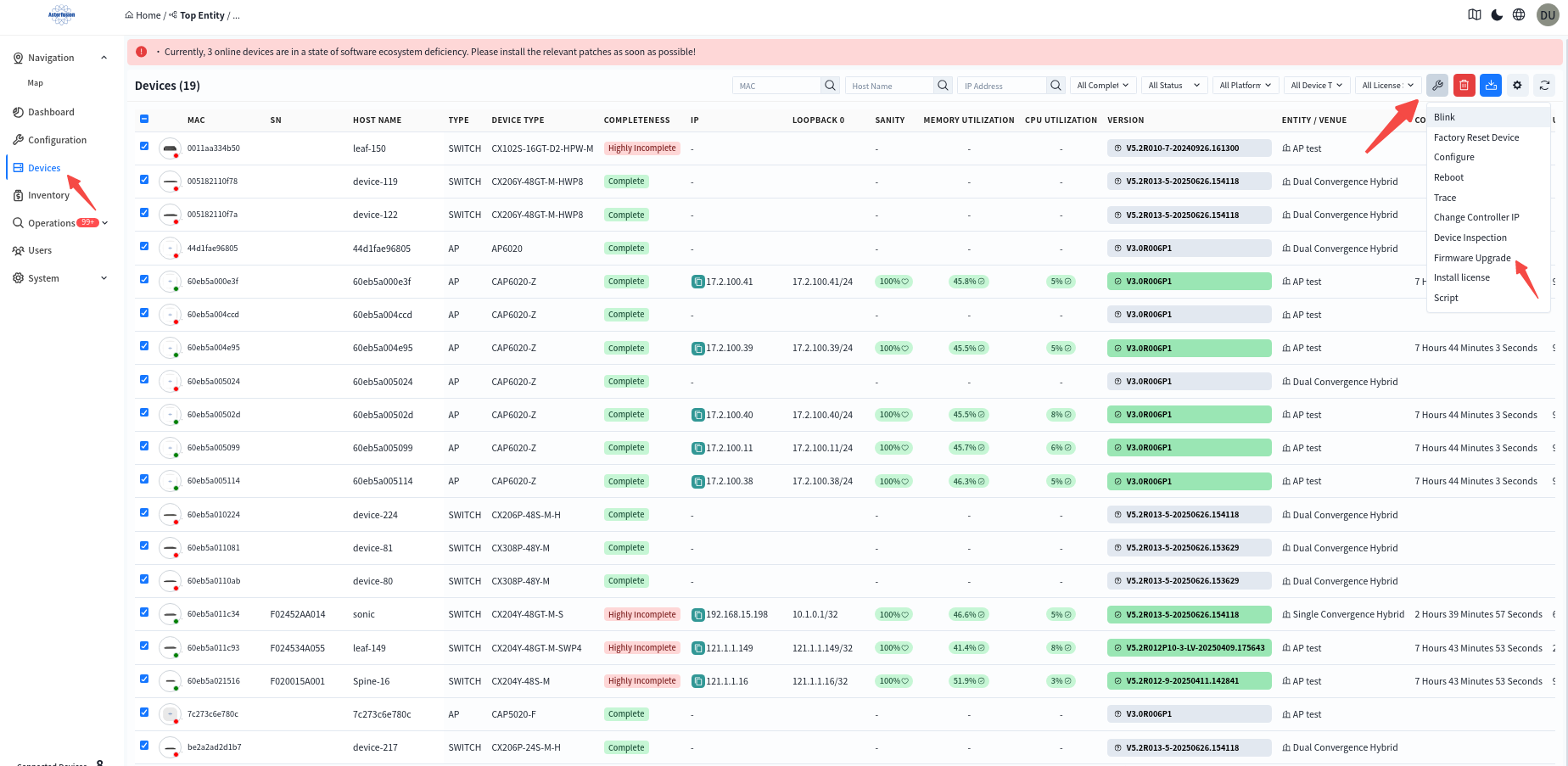
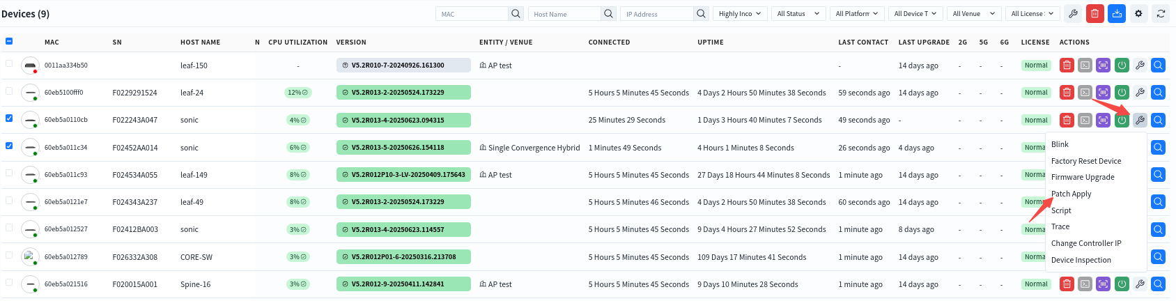
In the [Device] – [All] screen, the administrator can view the version information of all devices connected to the controller and compare it with the version description in [Firmware] to determine whether the device needs to be upgraded. The firmware image can be applied to the devices in the network individually or in batch.Select the devices that need to be upgraded. Click the [Firmware Upgrade] button.
In the pop-up window, select the firmware image file to perform the upgrade.
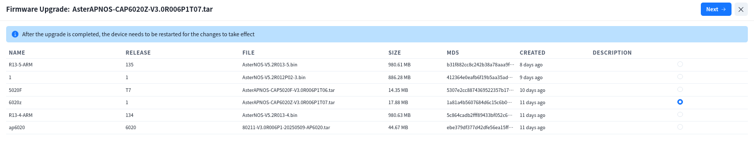
Note: The switch will not reboot automatically after the upgrade is completed, you need to manually perform the reboot operation to make the upgrade take effect.
7.2 Patch Management
Patch management allows administrators to upload patch files to the controller, The controller automatically parses the patch content to ensure that patches are applied to the correct device platforms, thereby enhancing network security and device stability.
Key Functions:
Manual Patch Upload: Administrators can upload patch files in various formats (such as .bin, .tar.gz, .patch).
Automatic Parsing: The system will extract version details, applicable device models, and dependencies to verify compatibility.

The administrator can view all devices that have not been patched in the [Devices] interface.
After selecting the device that needs to install the patch, click [Actions] – [Patch Apply] to install the patch.
8 Operations and alarm management #
Controller is equipped with powerful device status monitoring function, which can monitor the working status of switches and wireless APs in real time. Through the detailed dashboard display, administrators can grasp the operating status of the equipment at any time. Based on the acquired monitoring information, the controller evaluates various indicators and intelligently calculates the health value of each device. The health value is evaluated by considering the following factors:
Resource utilization: Based on the memory and CPU utilization, evaluate the use of device resources and whether there is a risk of resource exhaustion.
Traffic load: Based on traffic statistics, analyze the load of the device and determine whether there is a traffic bottleneck.
Hardware Status: Monitor the temperature of each component of the device, the operation of the power supply, fan and other hardware, whether it is within the expected range.
Running status: detect the running status of each major process and container of the device in real time.
When the monitoring index exceeds the preset threshold, the controller will automatically generate an alarm message to notify the administrator to ensure that the administrator can find and solve the problem in a timely manner to ensure the efficient, safe and stable operation of the network.
8.1 Comprehensive Visualization of Network Status
The controller supports full volume calculation of monitoring data from all online devices, and finally presents them globally as a comprehensive health value.
8.1.1 Organization Dashboard
Administrators can enter the specific organization in the [Navigation] screen to view an overview of the status of devices and terminals under all premises within the organization.
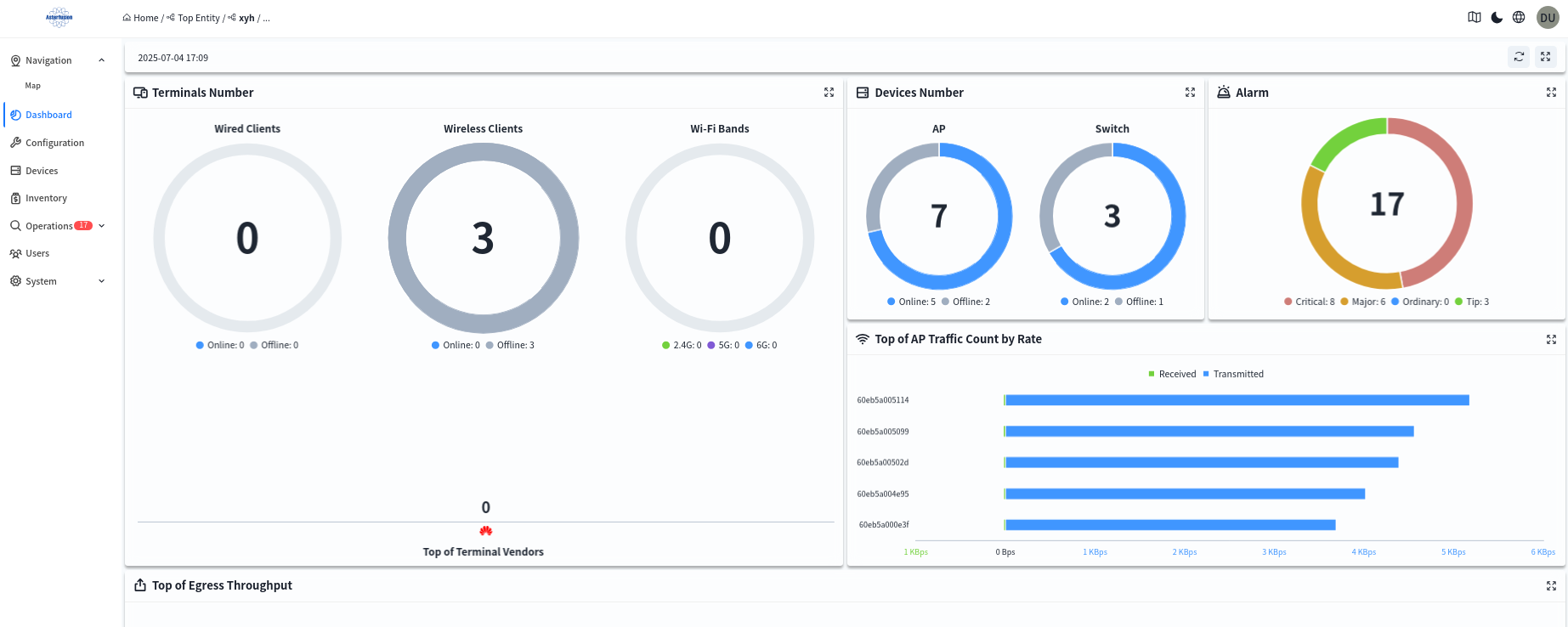
You can also click on any one of the devices under the [Device] – [All] screen to enter the management screen of the device and view the details of the device.
8.1.2 Venue Dashboard
Administrators can enter a specific venue under a specific organization in the [Navigation] interface to view an overview of the status of devices and terminals under all venues within the organization.
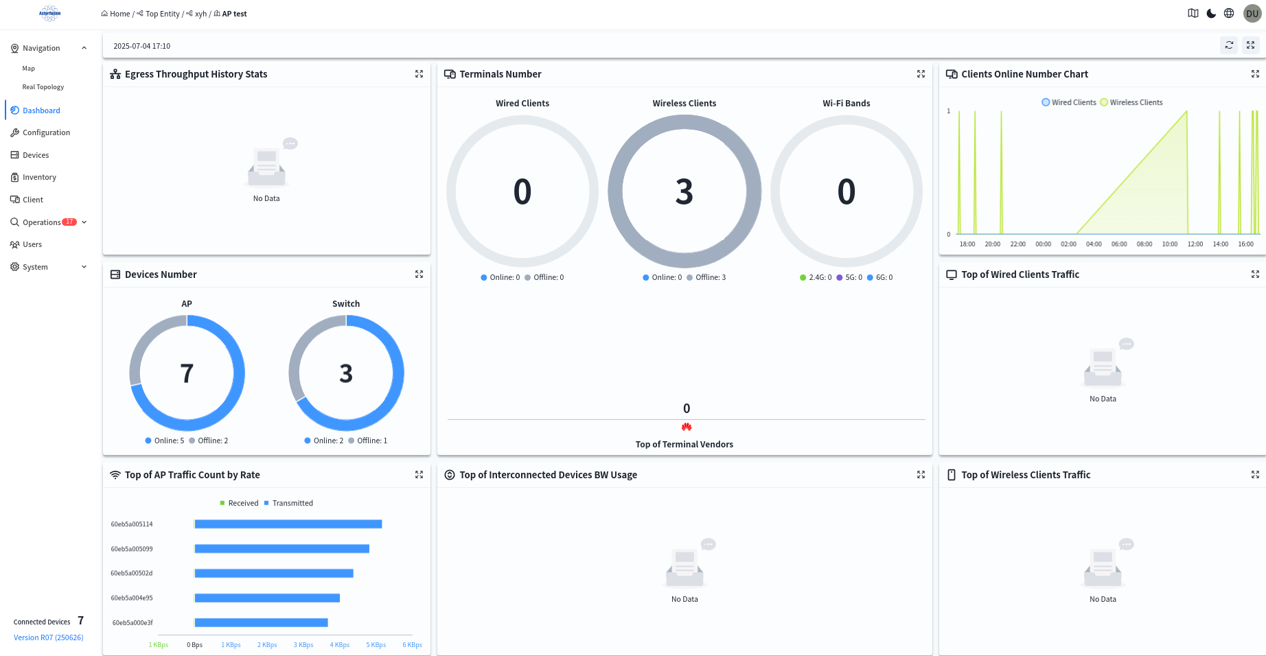
- Historical Statistics of Egress Throughput
Displays historical throughput statistics of the Spine up-link ports in this venue. - Device Quantity
Displays the online status and quantity of all devices in this venue. - Terminal Quantity
Displays the quantity of wired and wireless terminals in this venue; the number of terminals under each wireless radio frequency; and terminal manufacturer information. - Terminal Online Trend Chart
Displays the online quantity trend of wired and wireless terminals in this venue over a period of time. - Top Cumulative Data Traffic of Wired Terminals
Displays the top 5 cumulative data traffic of wired terminals in this venue over a period of time. - Top Cumulative Data Traffic of Wireless Terminals
Displays the top 5 cumulative data traffic of wireless terminals in this venue over a period of time. - Top Statistical Report of AP Uplink Port Traffic Rate
Displays the real-time top 5 AP uplink port traffic rates in this venue. - Top Bandwidth Utilization Rate of Interconnected Devices
Displays the top 5 bandwidth utilization rates of interconnection links between Spine and Leaf devices in this venue. - Memory Usage Rate
Shows the average memory usage rate of all devices in this venue. Click to view the memory usage rate of all devices, and click the MAC address of a device to jump to the management interface of the single device. - Association Count
Shows the number of wireless terminals connected to all wireless access points in this venue via 5G and 2G. Click to view the number of terminals connected to each wireless access point and the basic information of the access points. Click the MAC address of a device to jump to the management interface of the single device. - Device Statistics
Shows the top 10 ranking of all wireless access points in this venue based on the number of connected terminals or traffic statistics. - Real-time AP Data
Shows the terminal access status of each SSID under different frequency bands of each wireless access point. Click the MAC address to view detailed information. - Client Lifecycle
Searches for wireless terminals connected to the wireless access points in the current venue by MAC address, and views the terminal’s IP address, connection time, connected AP, traffic statistics, and other information.
8.2 Terminal Status Visualization
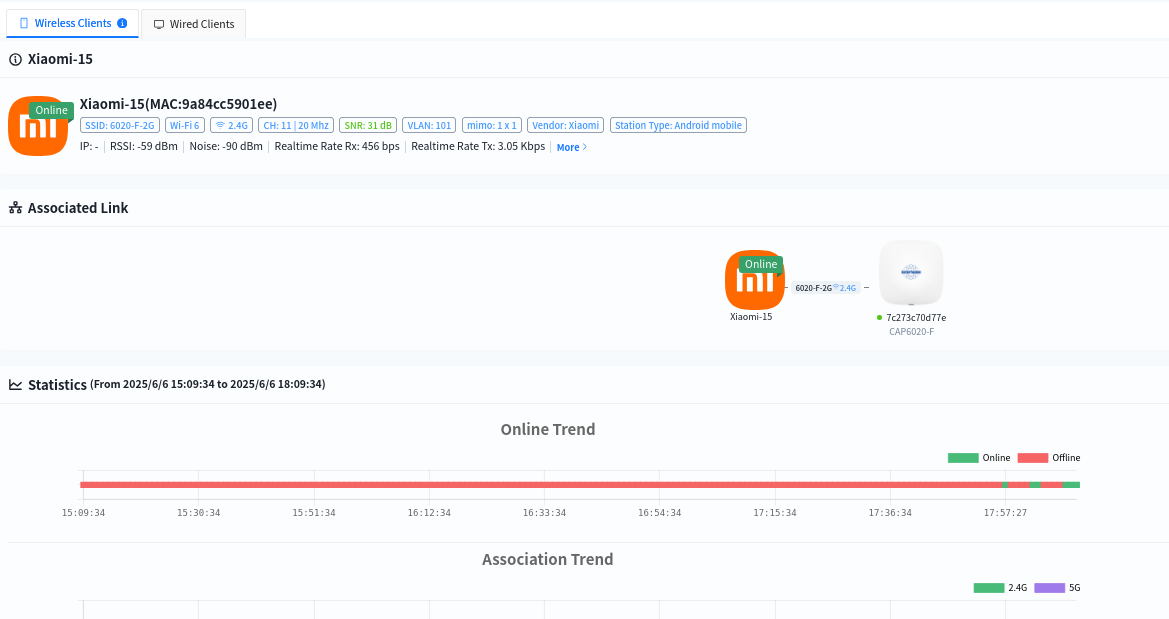
The controller supports collecting data of wired and wireless terminals online and visually presenting the status of online users. After entering a specified organization/venue, administrators can click [Client] to view information of all terminals under the organization/venue.
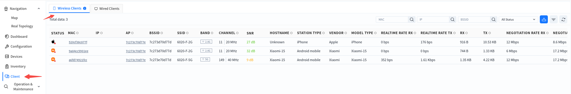
Click the MAC address of a client allows access to the detailed view to check specific data such as online trends, roaming records, and traffic statistics of the terminal. This helps administrators analyze the network connection status of the terminal within a specific time frame.
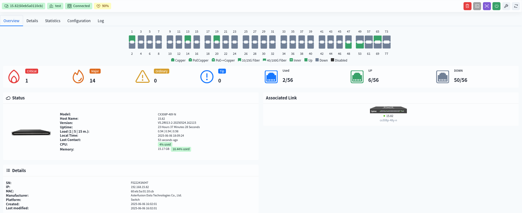
8.3 Device status visualization
Click [Device] – [Device MAC] to enter the management interface of the specified device and view the detailed information of this device:
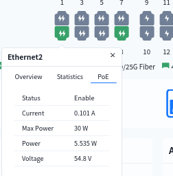
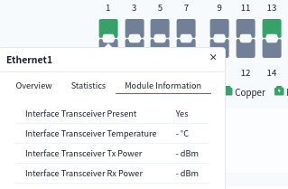
8.3.1 Interface Information
- View interface statistics
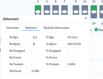
- view interface PoE power supply situation
- View interface optical module information
8.3.2 View device details
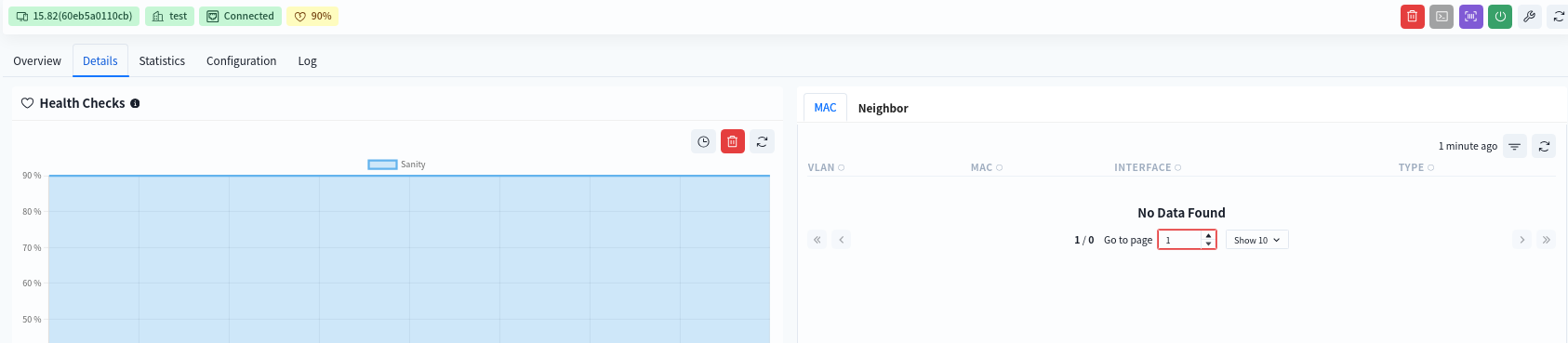
- Health Checks
The initial health check value for both the switch and the AP is 100%.
Health check calculation specification for the switch:
1.CPU utilization over 80%, soundness reduced by 10%
2.Memory utilization over 80%, soundness reduced by 10%
3.Switch chip/CPU temperature over 85°C, soundness reduced by 10%
4.PSU any one power supply status abnormality (power module not in position, power supply not powered), soundness minus 10%
5.Service detection: any critical business service abnormality, soundness minus 10%
AP Health Check Calculation Rule:
1.interface can successfully detect the DHCP/DNS server information is normal interface, integrity = normal interface / total number of interfaces
- table entry resources
- routing
- MAC
- Neighbor information (ARP)
- temperature information
- Fan information
- PSU power supply information
- Patches List of patches already installed on the device
- Remarks
8.3.3 View device statistics
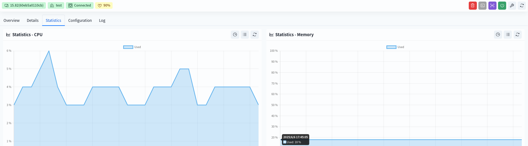
- CPU Statistics
Historical CPU statistics over a three-day period. - Memory Statistics
Historical memory statistics over a three-day period. - Interface Statistics
Single interface/whole interface statistics, support KB/s and PPS two kinds of statistics. - Transmission Rate
The top 10 interfaces of the current device, displaying the current transmission rate of the interface in the RX & TX direction. - POE Terminal
Connection information of POE terminals on the current device, including: host name of the terminal, access port number, terminal MAC, IP and other information, and support to view the historical number of POE terminals accessed on the specified port within 3 days. - LLDP
Display LLDP information on the switch.
8.4 Alarm Management
8.4.1 Alarm Item Configuration
Administrators can configure the recipients of alarm emails and alarm thresholds in the [Configuration] – [Operation&Maintenance Configuration] interface of the designated venue. By default, all alarms supported by the controller are enabled.
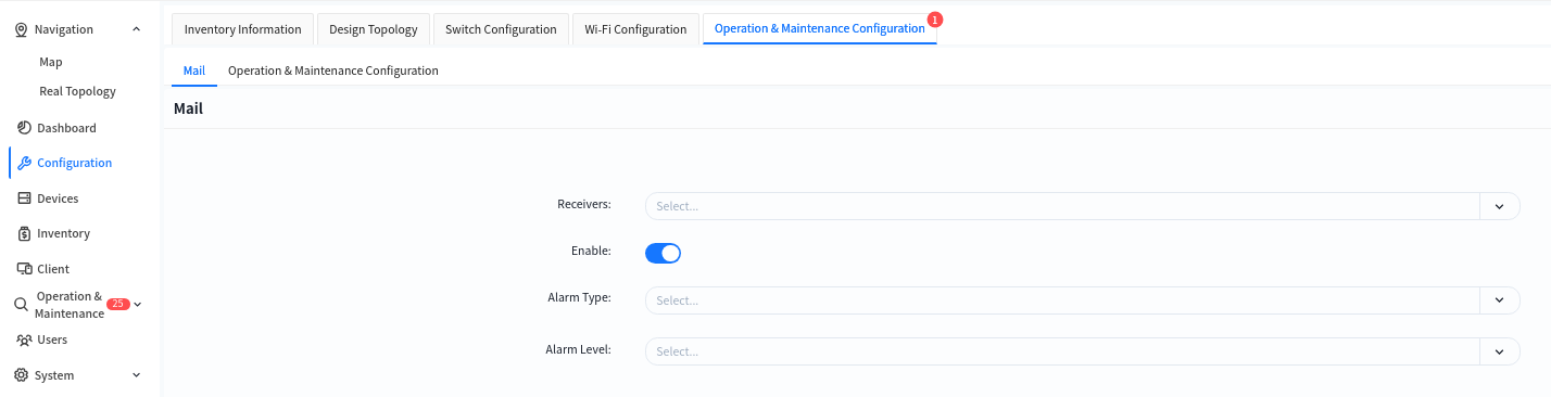
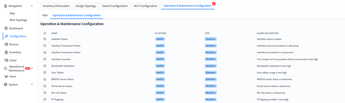
The controller supports the following alarms:
| Alarm Type | Alarm Item |
|---|---|
| Interface Status | Interface UP/Down status change |
| Wireless Terminal Type | Change in the vendor type corresponding to the MAC address |
| Interface Module Optical Power | Optical power of the optical module |
| Interface Module Status | Presence status of the interface module |
| Bandwidth Utilization | Bandwidth utilization rate |
| User Table Entries | ARP entry resource utilization IPv4-host-route: /32 host route entry resource utilization IPv4-route: Route entry resource utilization IPv6-host-route: /128 IPv6 host route entry resource utilization IPv6-route: IPv6 route entry resource utilization MAC entry resource utilization Route-nexthop: Next-hop resource utilization of route entries |
| RADIUS Sever Status | Detected operating status of the RADIUS server |
| PortalSever Status | Detected operating status of the Portal server |
| MC-LAGStatus | Operational status of the MC-LAG protocol |
| IP Flapping | Unusually frequent flapping of IP addresses across different switches |
| MAC Flapping | Unusually frequent flapping of MAC addresses on different interfaces of the same switch |
| Interface POE Status | Change in the POE status of the interface |
| POE Total Power Utilization | Percentage of current total power supply of the POE switch to the rated POE power supply |
| Device Connection Status | Change in the connection status between the device and the controller |
| CPU Utilization Rate | - |
| Memory Utilization Rate | - |
| Disk Utilization Rate | - |
| temperature | CPU core temperature FAN temperature PCB PCB temperature SWITCH switch chip temperature |
| Fan | Presence status of the fan module Fan speed |
| Psu | Presence status of the power supply module |
| Power | Power supply status |
| Core Dump File Status | Resource utilization rate of core dump files |
| Docker Status | Docker status on switch |
| BGP Connection Status | Change in the connection status of BGP neighbors on the switch |
| BFD Connection Status | Change in the connection status of BFD neighbors on the switch |
8.4.2 Mail Sender
Click [System] – [Mail Sender] to modify the source mailbox for sending alerts.
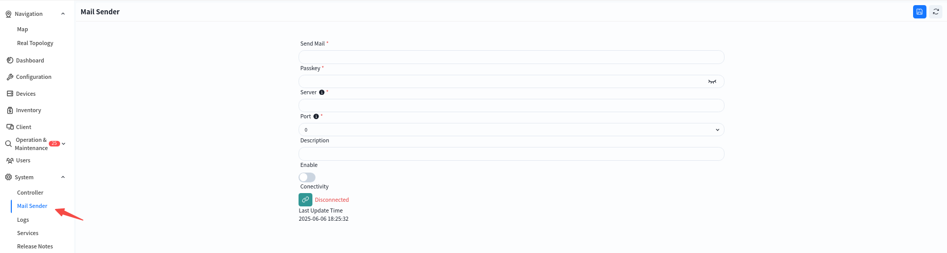
Click [Connectivity] to test the connectivity between the controller and the email server, preventing alarm emails from failing to be sent normally due to network connectivity issues.
8.4.3 Alarm Message
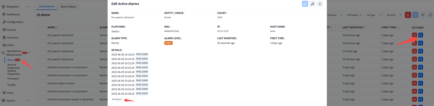
Administrators can view alarm information for all devices within their management authority in the [Operations and Maintenance] – [Alarm] interface.
- Active Alarms: Displays alarm items that still exist currently.
- Alarms History: Displays alarm items that showed abnormalities before but have returned to normal.
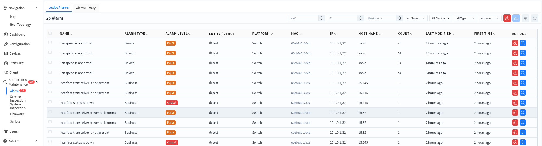
Click the alarm item to view specific alarm information and process it. Click the [Edit] button, fill in the processing information for the current alarm in the [Analysis] section, and click the [Save] button to complete the edit. After that, this alarm information will no longer be displayed in [Active Alarms] but will be stored as a processed alarm in [Alarm History].
8.5 Device Inspection
The device inspection feature is designed to regularly check and monitor network devices to ensure their normal operation and detect potential faults in a timely manner. Its main functions include:
- Device Status Monitoring: Checks critical parameters such as CPU usage, memory usage, storage, and port status to ensure devices are functioning properly.
- Log and Alarm Management: Collects device logs, analyzes abnormal events, and triggers alarm mechanisms.
- Critical Process Status Check: Monitors the status of essential processes to ensure smooth business operations.
- Automated Inspection Tasks: Supports scheduled inspection tasks, generates inspection reports, and facilitates network maintenance.
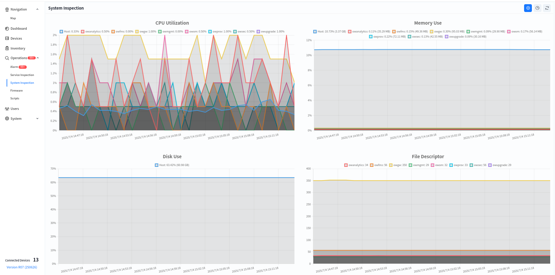
8.5.1 System Inspection
System inspection refers to the periodic check of the controller’s internal system to ensure stable and efficient operation. Key inspection items include:
- CPU & Memory Usage: Monitors CPU load and memory consumption to prevent system failures due to resource exhaustion.
- Disk Usage Check: Examines disk usage to prevent logs or cached data from consuming all available storage, which could impact system performance.
- Files Descriptor: Verifies the proper functioning of critical services (e.g., network management, authentication, logging) and automatically restarts abnormal processes.
- E-Mail Server Connected: Tests the controller’s connectivity with the email server to ensure alert notifications are successfully sent.
System inspections can be scheduled at fixed intervals (e.g., every 5 minutes or every hour) and automatically generate inspection reports for administrators to analyze and optimize system performance.
8.5.2 Business Inspection
Business inspection refers to periodic or on-demand checks of network device operation to ensure stable business operations and prevent potential failures.
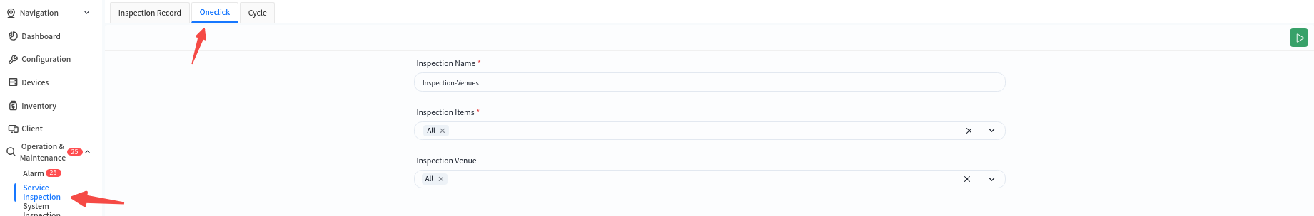
8.5.2.1 One-Click Inspection
This feature allows users to specify inspection items and target venues for an instant inspection, defining the scope of the inspection accordingly.
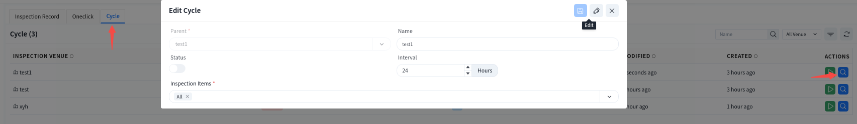
8.5.2.2 Cycle Inspection
Cycle inspection is configured based on the needs of different venues, allowing for automated inspections at scheduled intervals without manual intervention, thus improving operational efficiency. Click the [View Details] button to view/edit the periodic inspection settings for the selected venue.
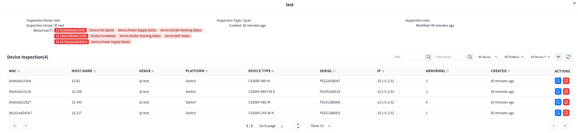
8.5.2.3 Inspection Records
Both one-click inspections and periodic inspections are logged in the inspection records.
Click the [View Details] button to check the inspection results. All detected anomalies will be listed under the [Abnormal] section. Administrators can:
Click [Actions] – [View Details] to check the inspection results of a specific device.
Click on the MAC address to directly navigate to the device management interface for further analysis.


Leave a Reply