RoCE Configuration on Asterfusion Enterprise SONiC Distribution Switch
1 Purpose
This article mainly explains the RoCE configuration and solution of Asterfusion enterprise SONiC switches.
2 Model and Version
Model:
CX-N series switches
Version:
AsterNOSv3.1
3 RoCE principles and configuration considerations
3.1 What is RoCE and its type
Asterfusion Low Latency Switches — The RoCE Ready Switch
3.2 RoCE introduction
In various HPC high-performance computing scenarios, the requirements for the network are basically two important characteristics: high throughput and low latency. In order to achieve high throughput and low latency, the industry generally uses RDMA (Remote Direct Memory Access). Memory access) replaces the TCP protocol. However, RDMA is very sensitive to packet loss. Once packet loss and retransmission occur, performance will drop sharply. Therefore, to ensure that RDMA throughput is not affected, the packet loss rate must be below 1e-05 (one in one hundred thousand), preferably zero packet loss.
RoCE (RDMA over Converged Ethernet) network uses PFC+ECN features to ensure that there is no packet loss during network transmission.
3.3 RoCE principles and configuration considerations
The RoCE network uses PFC+ECN to ensure network losslessness. The specific principles are as follows:
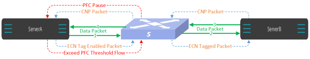
When serverA communicates with serverB, the normal data flow direction is as shown by the green solid line, from A to B through switch S, and then returns from B to A.
When packet congestion occurs, ECN needs to be enabled first. Set the ECN storage threshold range of the switch to N~M. When the server exceeds N, S starts to randomly mark ECN bits in the packet. When the server exceeds M, S Start marking ECN bits in all messages. After receiving the message marked with the ECN mark, B starts to send CNP messages to A, notifying A to reduce the sampling rate until the optimal sampling rate is found, and then continues to sample data at this rate, so as to achieve the purpose of not losing packets.
When packet congestion occurs, PFC will also play a role. Set the PFC queue threshold of the switch to Q. When the queue exceeds Q, the S switch will immediately continue to send PAUSE data frames to A. After A receives the PAUSE frame, it will stop immediately. Send a message to the queue of S. At this time, the data flow will be interrupted. When A no longer receives pause messages, it will resume sending messages to S.
Therefore, in order to reduce the impact of data interruption on business, we should try to avoid the triggering of PFC and use ECN to ensure data transmission. In this case, the storage threshold setting Q of the switch needs to be greater than M. Make sure ECN triggers before PFC.
4 Asterfusion Enterprise SONiC Distribution switch RoCE configuration
Asterfusion switches run the enterprise-level SONiC (AsterNOS) system and use PFC+ECN to ensure that the RoCE network is lossless.
There are two roce configuration methods:
4.1 Automatically configure RoCE parameters with one key
Example:
sonic# configure terminal
sonic(config)# qos roce lossless
sonic(config)# qos service-policy roce_lossless
It also provides one key viewing of all RoCE-related configuration information. The command is as follows:
sonic# show qos roce4.2 Manually configure RoCE parameters
When the configuration parameters of one key RoCE do not match the current scenario, you can also manually configure the parameters to achieve the best effect. The relevant configurations are as follows:
4.2.1 Modify DSCP mapping
diffserv-map type ip-dscp roce_lossless_diffserv_map
ip-dscp value cos cos_value


default {cos_value|copy}
# Enter DSCP mapping configuration view

# Configure the mapping from DSCP to COS. value specifies the DSCP value, rang 0-63; cos_value specifies the COS value, rang 0-7.
# default cos_value indicates that all data packets are mapped to the corresponding COS value; default copy indicates the system default mapping.
Example:
sonic# configure terminal
sonic(config)# diffserv-map type ip-dscp roce_lossless_diffserv_map
sonic(config-diffservmap-roce_lossless_diffserv_map)# ip-dscp 1 cos 1
sonic(config-diffservmap-roce_lossless_diffserv_map)# default copy
4.2.2 Modify queue scheduling policy
policy-map roce_lossless
queue-scheduler priority queue queue-id

queue-scheduler queue-limit percent queue-weight queue queue-id
# Enter related view
# Configure SP mode scheduling, queue-id represents the queue, range 0-7.
# Configure DWRR mode scheduling. queue-weight represents the scheduling weight percentage, rang 0-100; queue-id represents the queue, rang 0-7.
Example:
sonic# configure terminal
sonic(config)# policy-map roce_lossless
sonic(config-pmap-roce-lossless)# queue-scheduler priority queue 3
sonic(config-pmap-roce_lossless)# queue-scheduler queue-limit percent 60 queue 3
4.2.3 Adjust PFC waterline
buffer-profile roce_lossless_profile
mode lossless dynamic dynamic_th size size xoff xoff xon-offset xon-offset [xon xon]
# Enter PFC configuration view

# Modify PFC lossless Buffer
dynamic_th represents the dynamic threshold coefficient, range [-4,3]; dynamic threshold= 2dynamic_th×remaining available buffer. For example, if dynamic_th is set to 1, then the dynamic threshold is 2 times the remaining available buffer, which means the actual threshold is 2/3 of the total available buffer; size indicates the reserved size, measured in bytes, with a recommended configuration value of 1518.
xoff represents the triggering buffer threshold value for PFC pause frames, recommended to be configured as a multiple of the cell size (224 Bytes), measured in bytes. The value of xoff is related to parameters such as cable length and interface speed. xoff value must be greater than xon value.
xon-offset represents the stop buffer threshold value for PFC pause frames, recommended to be configured as a multiple of the cell size (224 Bytes), measured in bytes. The recommended configuration value is 13440.
xon is an optional parameter typically configured as 0.
Example:
sonic# configure terminal
sonic(config)# buffer-profile roce_lossless_profile
sonic(config-buffer-profile-roce_lossless_profile)# mode lossless dynamic 1 size 1518 xoff 896 xon-offset 13440 xon 0
4.2.4 Adjust ECN waterline
wred roce_lossless_ecn
mode ecn gmin min_th gmax max_th gprobability probability [ymin min_th ymax max_th yprobability probability|rmin min_th rmax max_th rprobability probability]
# Enter the ECN configuration view
# Modify ECN parameters:
min_th sets the lower absolute value for explicit congestion notification, measured in bytes. When the length of packets in the queue reaches this value, the interface begins to probabilistically set the ECN field of packets to CE. The minimum configurable min threshold value is 15KB, with a recommended configuration value of 15360 bytes.
max_th sets the upper absolute value for explicit congestion notification, measured in bytes. When the length of packets in the queue reaches this value, the interface starts setting the ECN field of all packets to CE. Recommended values for different interface rates are as follows: 100/200G is 76800, 400G is 1536000.
probability sets the maximum probability of setting the ECN field of packets to CE, in integer form, range [1, 100]. For delay-sensitive business, it is recommended to set the maximum discard probability to 90%; for throughput-sensitive business, it is recommended to set it to 10%.
Example:
sonic# configure terminal
sonic(config)# wred roce_lossless_ecn
sonic(config-wred-roce_lossless_ecn)# mode ecn gmin 15360 gmax 76800 gprobability 90
5 User test case
5.1 Requirements
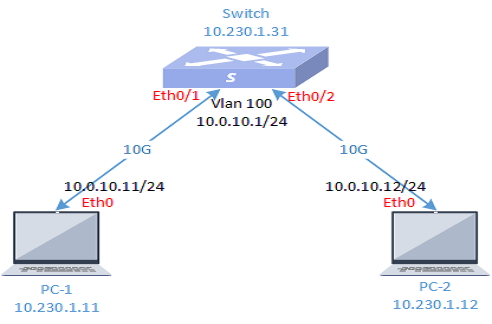
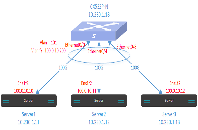
Currently, there are three servers installed with Mellanox 100G network cards. The objective is to test the lossless forwarding feature of the CX532P-N switch, as depicted in the diagram below. Server 1 will send RDMA traffic through the switch’s lossless queue forwarding to Server 3, while Server 2 will send regular TCP traffic through the switch to Server 3. The goal is to observe the data reception status.
5.2 Topology

5.3 Testing environment
5.3.1 Hardware
| NAME | MODEL | HARDWARE INDICATORS | QUANTITY | NOTE |
|---|---|---|---|---|
| Optical fiber | Multi-mode | 100G | 3 | |
| Network Card | MCX653195A-ECAT | 100G | 3 | |
| Optical module | Multi-mode | 100G QSFP28 | 6 | |
| Server | X86 | Normal server | 3 | Installed 100G Mellanox card |
| Switch | CX532P-N | Refer to Product manual | 1 |
5.3.2 software
| SOFTWARE | VERSION | NOTE |
|---|---|---|
| Switch system | AsterNOSv3.1 | |
| Server System | OpenEuler 22.03 | |
| Server Kernel | 5.10.0-136.33.0.109 | |
| Mellanox Card Driver | 5.10.0-60.18.0 | Card driver version needs to be compatible with server kernel version. |
5.3.3 Management IP
| DEVICE NAME | INTERFACE | IP ADDRESS | NOTE |
|---|---|---|---|
| CX532P-N | Mgmt0 | 10.230.1.18 | |
| Server-1 | Eth0 | 10.230.1.11 | |
| Server-2 | Eth0 | 10.230.1.12 | |
| Server-3 | Eth0 | 10.230.1.13 |
5.3.4 Device communication IP
| DEVICE NAME | INTERFACE | IP ADDRESS | NOTE |
|---|---|---|---|
| CX532P-N | Vlanif | 100.0.10.200 | |
| Server-1 | ens1f2 | 100.0.10.10 | Mellanox card interface |
| Server-2 | ens1f2 | 100.0.10.11 | Mellanox card interface |
| Server-3 | ens1f2 | 100.0.10.12 | Mellanox card interface |
5.4 Preparation before testing
Connect each server to the switch according to the topology diagram, ensuring that Mellanox network cards and drivers are properly installed on the servers, and also install the iperf3 testing tool.
5.5 Configuration step
Step 1
Perform basic configuration on the switch to ensure that the three interfaces are in the same Layer 2 network and that data can be forwarded properly.
sonic# configure terminal
sonic(config)# vlan 101
sonic(config-vlan-101)# interface ethernet 0/0
sonic(config-if-0/0)# switchport access vlan 101
sonic(config-if-0/0)# interface ethernet 0/4
sonic(config-if-0/4)# switchport access vlan 101
sonic(config-if-0/4)# interface ethernet 0/8
sonic(config-if-0/8)# switchport access vlan 101
sonic(config-if-0/8)# exit
sonic(config)# interface vlan 101
sonic(config-vlanif-101)# ip address 100.0.10.200/24
Step 2
One key configure RoCE parameters on the switch.
sonic# configure terminal
sonic(config)# qos roce lossless
sonic(config)# qos service-policy roce_lossless
Check the RoCE configuration on the switch.
sonic# show qos roce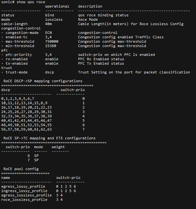
Step 3
Configure IP addresses for the three servers and configure RoCE parameters for the network cards. Use Queue 3 for the lossless queue in this case.
[admin@Server1~]# sudo ifconfig ens1f2 100.0.10.10/24 up
[admin@Server2~]# sudo ifconfig ens1f2 100.0.10.11/24 up
[admin@Server3~]# sudo ifconfig ens1f2 100.0.10.12/24 up
[admin@Server1~]# sudo mlnx_qos -i ens1f2 –trust dscp
[admin@Server1~]# sudo mlnx_qos -i ens1f2 –pfc 0,0,0,1,0,0,0,0
[admin@Server1~]# sudo cma_roce_mode -d mlx5_0 -p 1 -m 2
[admin@Server1~]# sudo echo 96 > /sys/class/infiniband/mlx5_0/tc/1/traffic_class
[admin@Server1~]# sudo cma_roce_tos -d mlx5_0 -t 96
[admin@Server1~]# sudo echo 1 > /sys/class/net/ens1f2/ecn/roce_np/enable/3
[admin@Server1~]# sudo echo 1 > /sys/class/net/ens1f2/ecn/roce_rp/enable/3
[admin@Server1~]# sudo echo 16 > /sys/class/net/ens1f2/ecn/roce_np/cnp_dscp
[admin@Server1~]# sudo sysctl -w net.ipv4.tcp_ecn=1
[admin@Server3~]# sudo mlnx_qos -i ens1f2 –trust dscp
[admin@Server3~]# sudo mlnx_qos -i ens1f2 –pfc 0,0,0,1,0,0,0,0
[admin@Server3~]# sudo cma_roce_mode -d mlx5_0 -p 1 -m 2
[admin@Server3~]# sudo echo 96 > /sys/class/infiniband/mlx5_0/tc/1/traffic_class
[admin@Server3~]# sudo cma_roce_tos -d mlx5_0 -t 96
[admin@Server3~]# sudo echo 1 > /sys/class/net/ens1f2/ecn/roce_np/enable/3
[admin@Server3~]# sudo echo 1 > /sys/class/net/ens1f2/ecn/roce_rp/enable/3
[admin@Server3~]# sudo echo 16 > /sys/class/net/ens1f2/ecn/roce_np/cnp_dscp
[admin@Server3~]# sudo sysctl -w net.ipv4.tcp_ecn=1
Step 4
Use Server1 and Server2 to send packets to Server3. Server1 sends RoCE traffic, while Server2 sends TCP traffic.
[admin@Server3~]# ib_send_lat -R -d mlx5_0 -F –report_gbits -a
[admin@Server1~]# ib_send_lat -a -R -x 3 -d mlx5_0 -F -f 2 100.0.10.12
[admin@Server3~]# iperf3 -s
[admin@Server2~]# iperf3 -c 100.0.10.12 -l 20k -b 100G -M 9000 -t 1000
Check the data forwarding status of each queue on the three interfaces.
sonic# show counters queue 0/0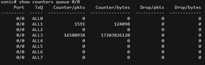
sonic# show counters queue 0/4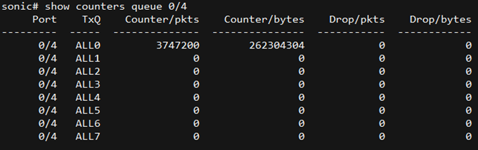
sonic# show counters queue 0/8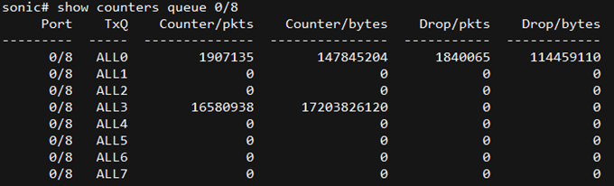
6 Conclusion
The forwarding results indicate that RoCE traffic forwarded through Queue 3 did not experience packet loss, while TCP traffic forwarded through Queue 0 experienced packet loss due to insufficient bandwidth.The CX532P-N switch can achieve lossless network transmission through its RoCE functionality, and its roce configuration is very simple.
Asterfusion CX-N & CX-M SONiC switches as the links below
CX-N series switches
CX-M series switches
If you have more technical questions, feel free to propose a ticket on our https://help.cloudswit.ch/portal/en/signin