Asterfusion Campus network implementation – Part Three Detailed Planning and Implementation
1 purpose
In order to introduce the method of deploying the entire campus network using Asterusion CX-M series products and controller products, we have written a series of documents on campus network planning, installation, implementation, and testing acceptance. By reading these documents, users can easily and quickly plan and deploy the campus network online. Once the user has already planned the overall network and prepared for the launch, they can deploy the entire network online within 30 minutes. This article is part three: detailed planning and implementation; This mainly elaborates on the planning and design of specific network topologies based on the engineering survey situation of each research and development center, as well as the pre configuration work and network implementation work before going online.
2 WH office network planning
Let’s start with the planning of the WH campus network. The following is the specific planning, design, and implementation process of the WH campus network.
2.1 Requirements
The current staff size of WH campus is about 50 people, and the office area is about 400 square meters, including two computer rooms, two conference rooms, and an open office area. There are approximately 70 server equipment for research and development.
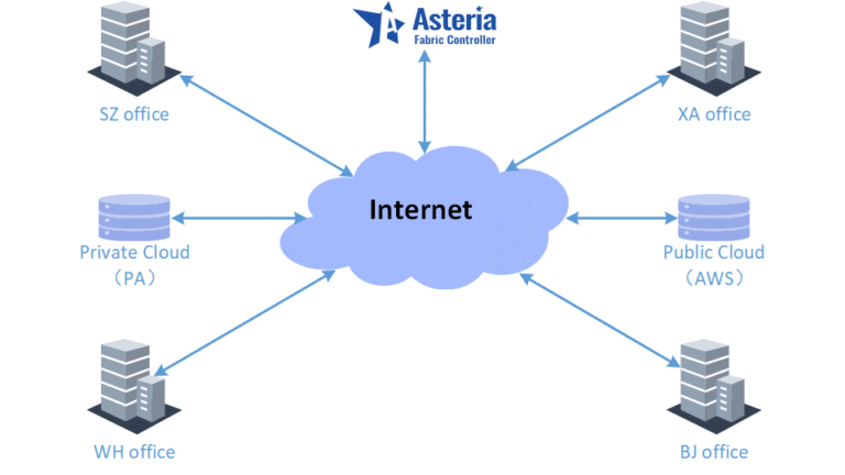
The newly built campus network needs to meet the networking needs of office staff and R&D servers. The Internet outlet uses two channels, one for dial-up Internet access and one for dedicated lines. At the same time, it is also necessary to meet the interconnection between the WH office campus and the cloud R&D server and other city office networks.
The specific construction survey information of WH campus is shown in the table below:
| Condition | Value | Note |
|---|---|---|
| Number of employees | 50 | |
| Office area | 400 square meters | 2 Equipment room,2 meeting room |
| Server | 70 | |
| Wired terminal | 50 | |
| Wireless terminal | 100 |
2.2 WH campus network device planning
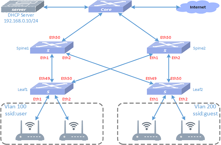
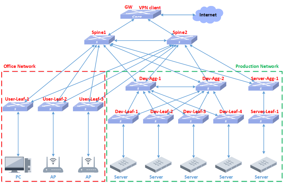
According to the specific engineering survey information, the number of required equipment is calculated to be 10, 2 spine switches, 4 leaf switches, 3 APs, and 1 smart gateway GW. The leaf-1 and leaf-2 devices are used for access to the R&D server. Leaf-3 and leaf-4 are used for access to user wired terminals and APs. There are 3 APs, one of which mainly covers two conference rooms, and the other two cover the open office area and computer room. The intelligent gateway GW device is responsible for egress routing, VPN and DHCP Server services.
2.3 WH Network topology
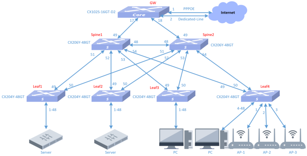
2.4 WH network equipment and versions
Model:
CX206Y-48GT-M switches
CX204Y-48GT-M switches
CX102S-16GT-D2-HPW-M switches
CAP6020-Z (AP)
Version:
CX206Y-48GT-M : AsterNOSv5.2R009P01
CX204Y-48GT-M : AsterNOSv5.2 R009P01
CX102S-16GT-D2-HPW-M:AsterNOSv5.2 R011
CAP6020-Z : TIP-V3.0R003P1
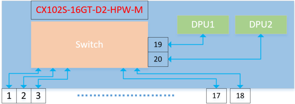
2.5 Introduction to GW equipment CX102S-16GT-D2-HPW-M
The CX102S smart gateway device has 161GE, 210GE interfaces, and is equipped with 2 DPU cards. This deployment uses this device as a gateway, deploys the Openwrt system on DPU1 to implement the routing gateway function, and uses the system-integrated wireguard component to implement it. VPN function. Deploy openclash and ntopng systems on DPU2 to realize network business proxy and network traffic graphical presentation functions.
The product diagram is as follows:
To learn more about this product please click on the link: https://cloudswit.ch/product/sonic-switch-add-marvell-octeon-tx2-cn9130-dpu/
2.6 WH network interconnection IP address planning
2.6.1 Device interconnection address
| Local device | Local port | Local IP | Remote device | Remote port | Remote IP | Note |
|---|---|---|---|---|---|---|
| Spine1 | 48 | 2.2.2.1/30 | Spine2 | 48 | 2.2.2.2/30 | Peerlink |
| Spine1 | 49 | 172.16.11.33/29 | GW | 17 | 172.16.11.36/29 | |
| Spine2 | 48 | 2.2.2.2/30 | Spine1 | 48 | 2.2.2.1/30 | Peerlink |
| Spine2 | 49 | 172.16.11.33/29 | GW | 18 | 172.16.11.36/29 | |
| Leaf1 | 1-48 | Vlanif:10.250.0.1 | Server | 10.250.0.0/24 | Manually configure IP | |
| Leaf2 | 1-48 | Vlanif:10.250.0.1 | Server | 10.250.0.0/24 | Manually configure IP | |
| Leaf3 | 1-48 | Vlanif:192.168.23.1 | Youxian-user | 192.168.23.0/24 | ||
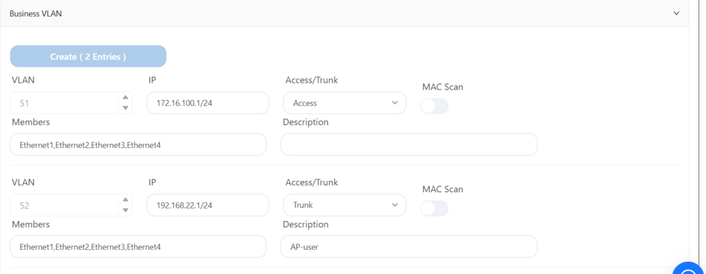
| Leaf4 | 1-4 | Vlanif:172.16.100.1 | AP-mgmt | 172.16.100.0/24 | ||
| Leaf4 | 5-48 | Vlanif:192.168.23.1 | Youxian-user | 192.168.23.0/24 | ||
| GW | 17 | 172.16.11.36/29 | Spine1 | 49 | 172.16.11.33/29 | |
| GW | 18 | 172.16.11.36/29 | Spine2 | 49 | 172.16.11.33/29 | |
| GW | 19 | Openwrt | 172.16.11.34/29 | Internal interface | ||
| GW | 20 | Ntopng | 172.16.11.35/29 | Internal interface | ||
| GW | 1 | VLAN101 pppoe | ||||
| GW | 2 | VLAN102 zhuanxian |
2.6.2 Device loopback address
| Device | IP address |
|---|---|
| Spine1 | 172.16.1.1/32 |
| Spine2 | 172.16.1.2/32 |
| Leaf1 | 172.16.1.3/32 |
| Leaf2 | 172.16.1.4/32 |
| Leaf3 | 172.16.1.5/32 |
| Leaf4 | 172.16.1.6/32 |
| GW | 172.16.1.7/32 |
2.6.3 Device VLAN information
| Vlan | IP address | Note |
|---|---|---|
| 200 | 172.16.11.36/29 | Interconnect with spine |
| 51 | 172.16.100.1/24 | AP management gateway |
| 52 | 192.168.22.1/24 | Wireless user gateway |
| 53 | 192.168.23.1/24 | Wired user gateway |
| 54 | 10.250.0.254/24 | Server gateway |
2.6.4 AP and user terminal equipment addresses
| Name | Vlan | Gateway | Dhcp poor | DNS |
|---|---|---|---|---|
| AP-mgmt | 51 | 172.16.100.1 | 172.16.100.2-254 | 218.104.111.111 |
| AP-user | 52 | 192.168.22.1 | 192.168.22.2-254 | 218.104.111.111 |
| Youxian-user | 53 | 192.168.23.1 | 192.168.23.2-254 | 218.104.111.111 |
| server | 54 | 10.250.0.254 |
2.7 WH network equipment and consumables table
| Name | Model | Describe | Quantity |
|---|---|---|---|
| Switch | CX206Y-48GT-HPW4-M | 48*1GE,6*10GE | 2 |
| Switch | CX204Y-48GT-HPW2-M-AC | 48*1GE,4*10GE,POE | 4 |
| AP | CAP6020-Z | Ceiling AP | 3 |
| Optical module | OM-10G-MM850-300-LC | 10G Multimode | 20 |
| Gateway | CX102S-16GT-D2-HPW-M | 16*1GE,2*10GE | 1 |
| Optical fiber | Multimode Fiber | 10GE Multimode | 10 |
| Network cable | Cable | Category 6 Ethernet cable | 150 |
3 Network planning on the controller
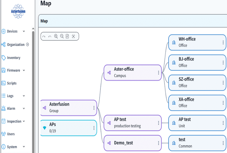
3.1 Establish organization and office space
Firstly, establish the root organization as follows:
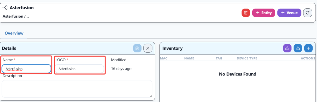
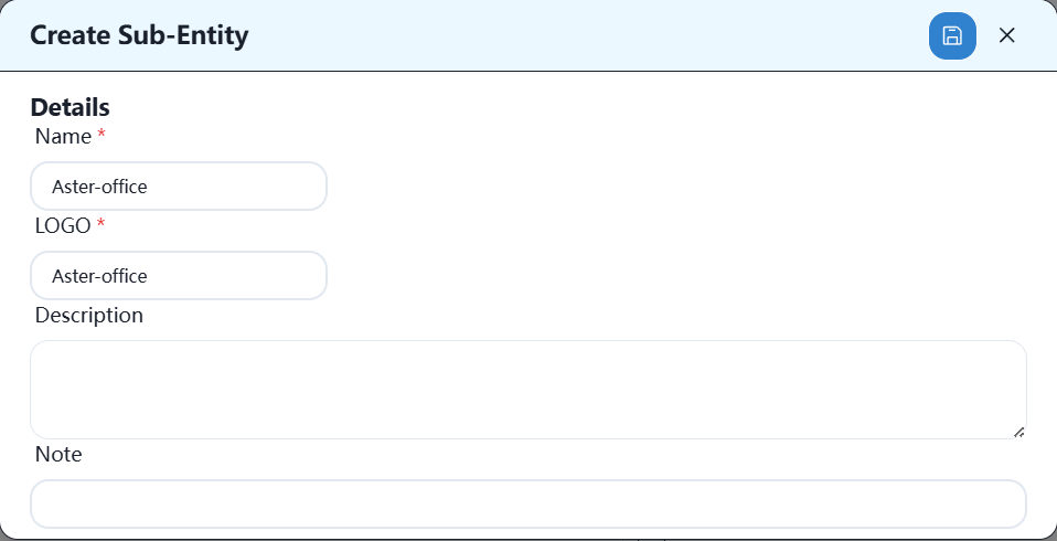
Then establish a company network organization as follows:
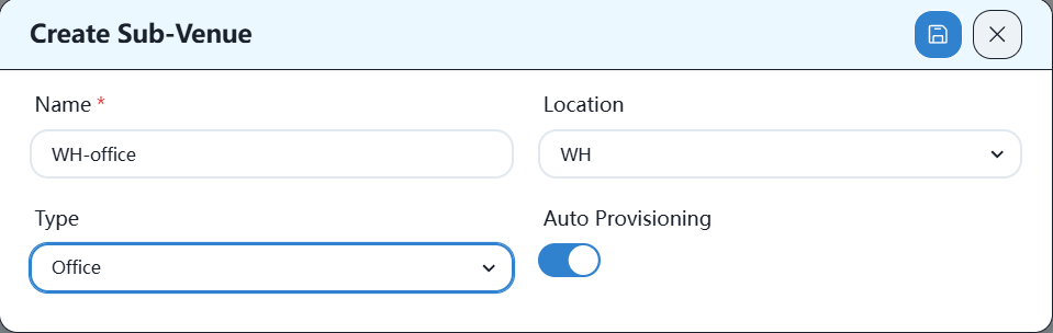
Then establish office locations, as follows:
3.2 Importing Equipment into Controller Warehouse
There are two ways to import devices into the controller warehouse: one is to manually add the import, and the other is to import from an Excel spreadsheet.
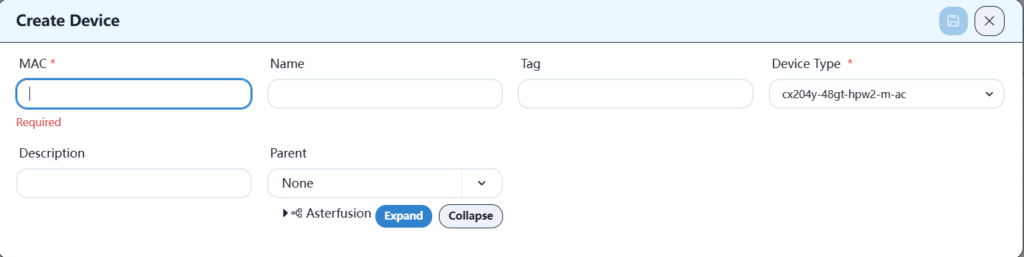
3.2.1 Manually add
Equipment can be manually added to the warehouse column of the corresponding location or the warehouse column under the root directory, as shown below:
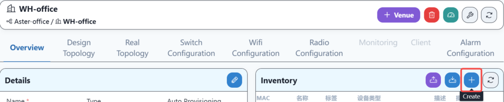
Please fill in the specific information as follows:
3.2.2 Import Excel spreadsheets
Record the MAC address and device model information of the devices that need to be launched into an Excel spreadsheet, and then import them into the controller in the following format:
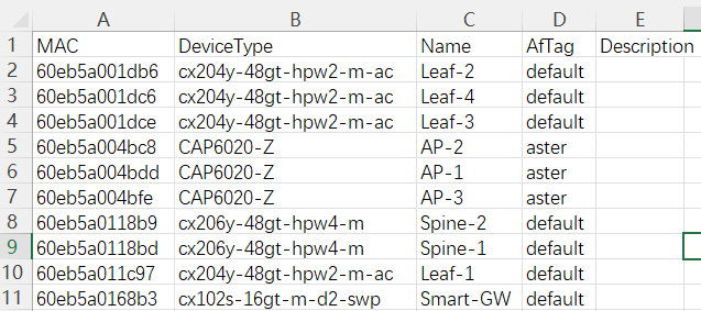
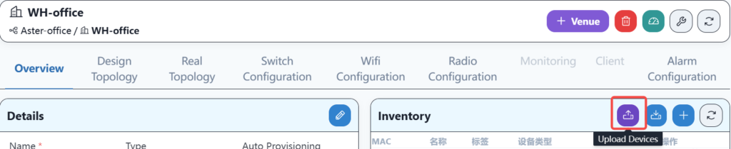
The file needs to be imported under the equipment warehouse column of the corresponding location, as shown below:
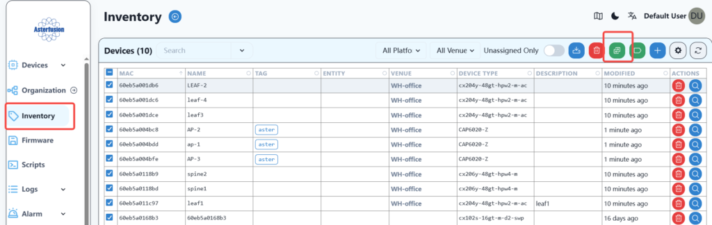
3.3 Importing warehouse equipment into the office space
If the device is imported through an Excel file in the office, this step is no longer required, and the device can be ensured to be in the corresponding location.
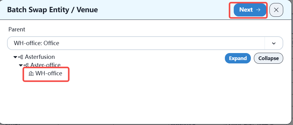
First, check all the devices to be imported to the specified location, and then click the batch import location button, as shown below:
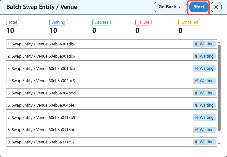
After the import is complete, you can plan the topology on the controller.
3.4 Planning Topology on Controller
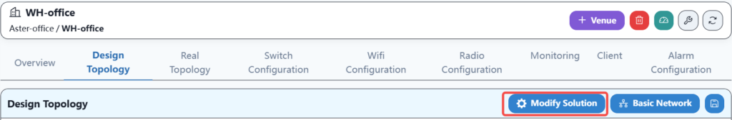
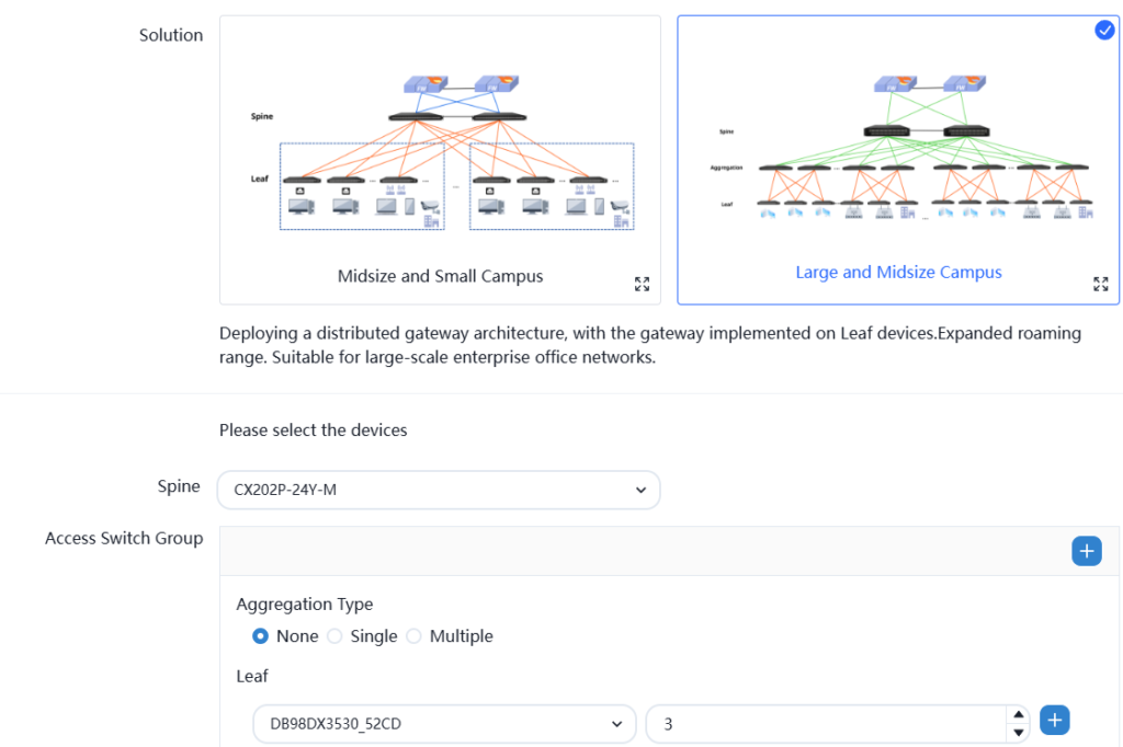
Firstly, in the WH office setting, select a network solution as follows:
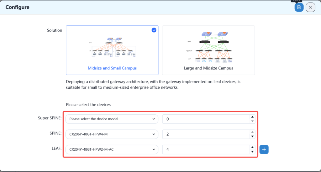
According to the plan, select the number of spins and leaves.
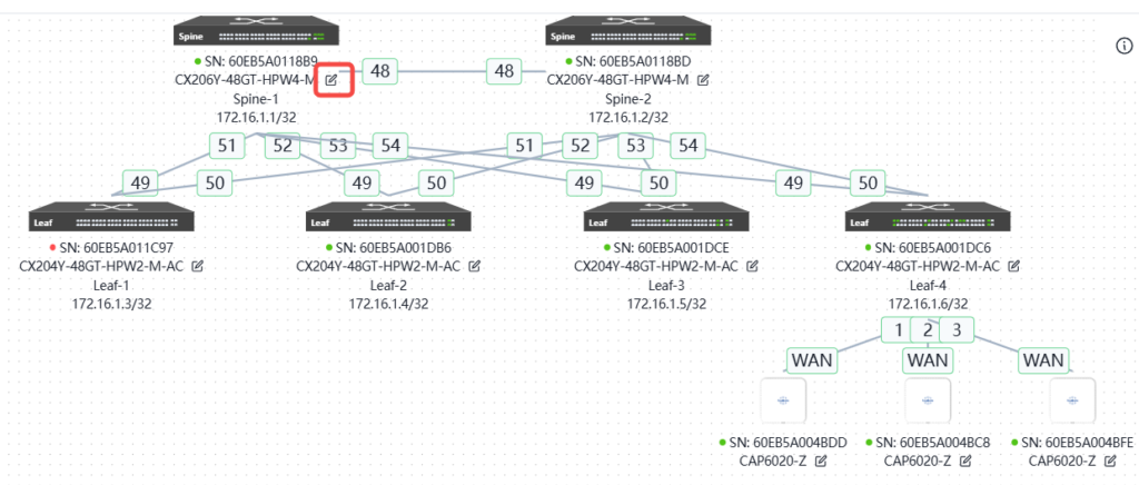
Then plan the network topology, drag the devices in the warehouse into the blank space on the right, and connect them to complete the network topology planning.
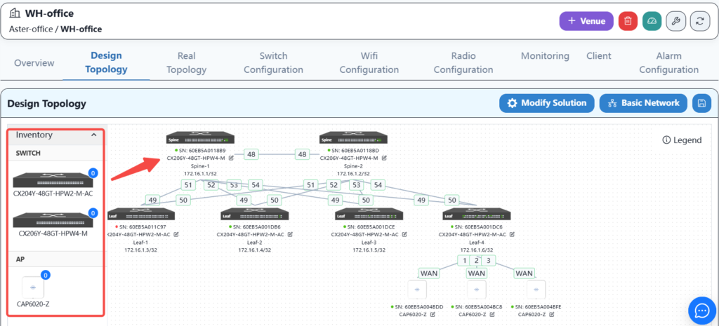
And by clicking the edit button on each device, you can configure the basic information and interconnection interface of the device, as follows
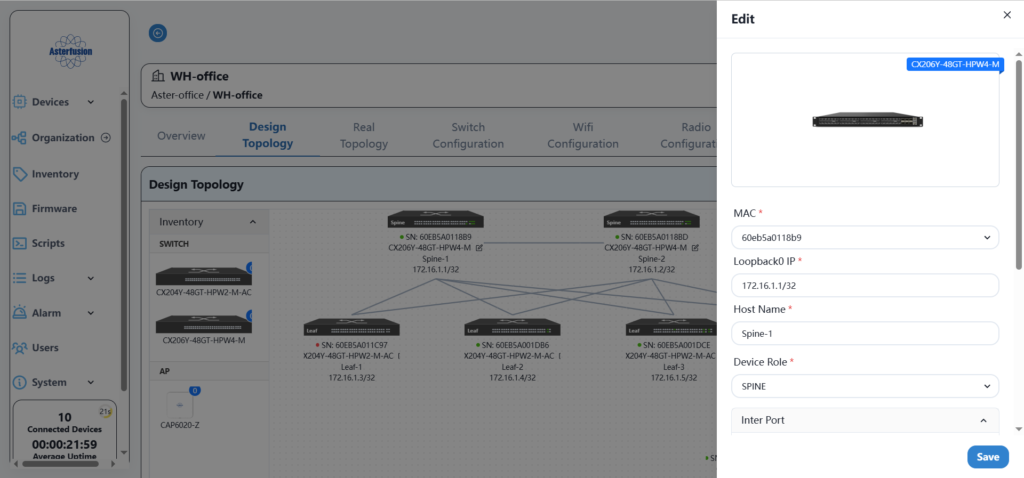
According to the network planning in section 3, fill in the basic configuration information of all devices in sequence.
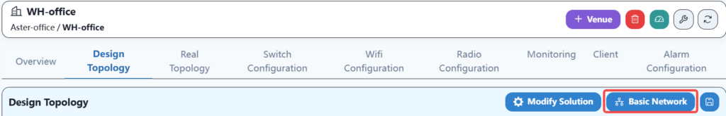
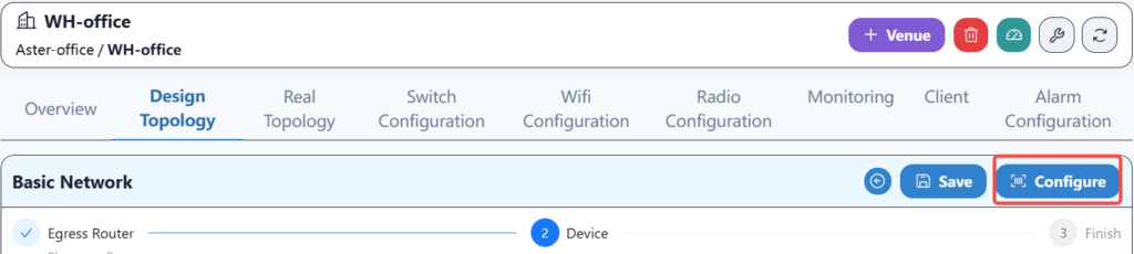
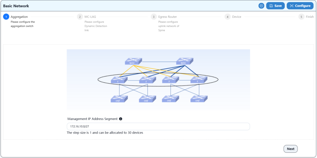
3.5 Basic network configuration
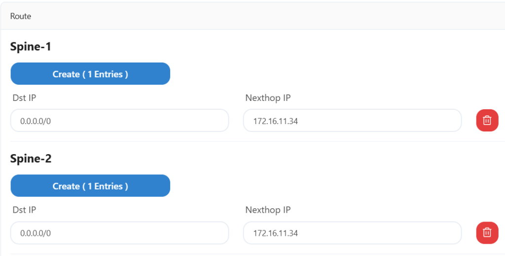
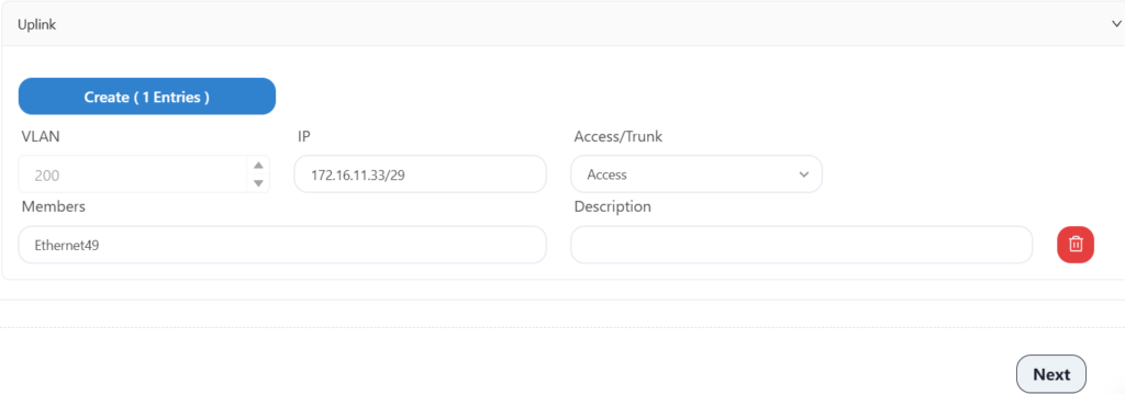
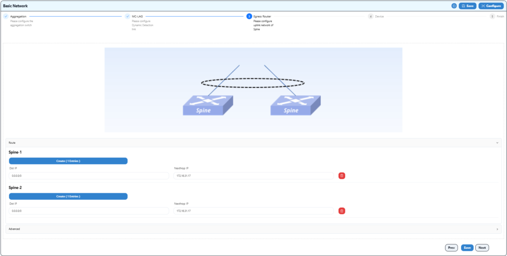
The basic network configuration mainly involves configuring the uplink information of spine devices to ensure correct network configuration with gateway devices.
Configure the gateway address of the upstream device here.
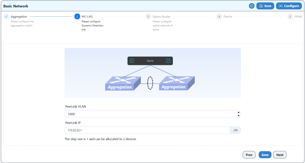
Configure two spine devices and an export gateway device for MC-LAG interconnection here.
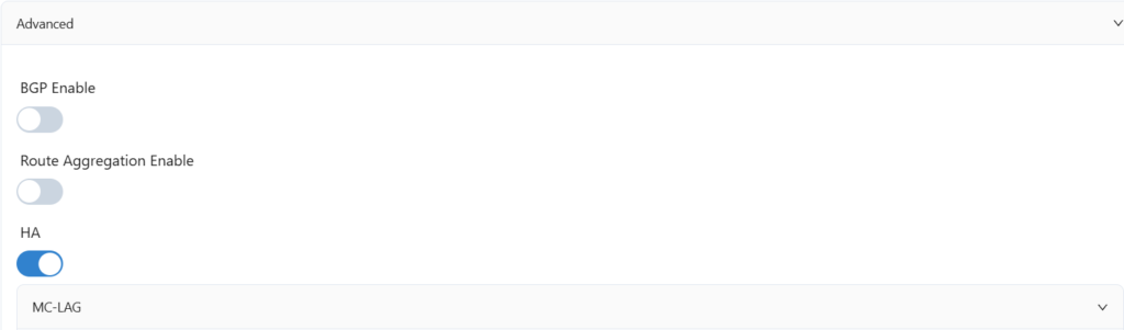
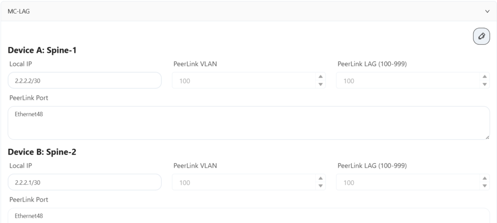
Configure the IP address and VLAN information of the HA uplink port here.
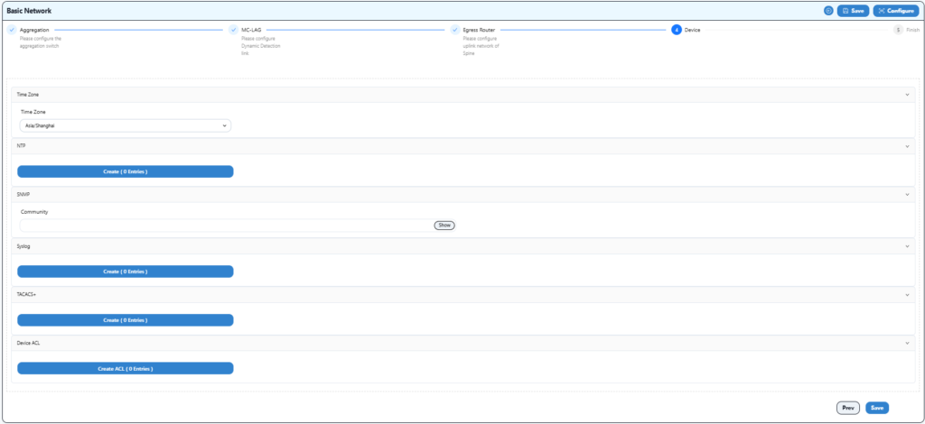
Configure time zone and NTP information here.
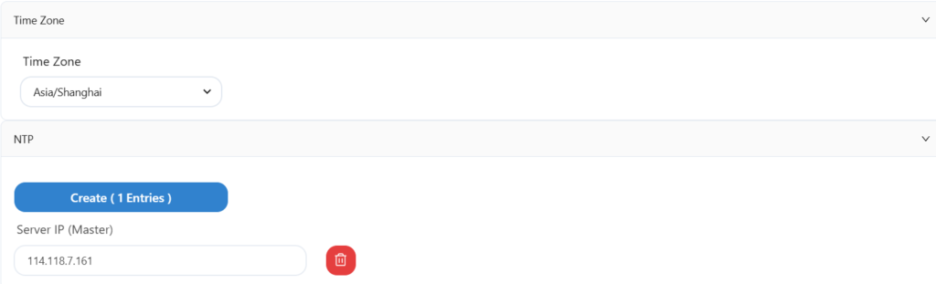
Save after configuration.
After completing the above steps, you can proceed to the implementation phase of the plan.
4 WH office network Implementation
4.1 Equipment shelving and comprehensive wiring
1.Install the equipment in the correct position of the cabinet in the computer room.
2.Install the AP at the planned location in the office area.
3.Carry out integrated wiring for all wired devices and workstations in the office area to ensure that the network cables are available normally.
4.2 Power on the device
1.Ensure that the devices are correctly connected according to the topology in Section 2.3.
2.Power on all devices.
4.3 Device and controller connection
4.3.1 Configure temporary IP addresses for two spine and the GW device
Configure the temporary IP of the uplink of the two spine devices and the routing information of the GW gateway to ensure that the two spine devices can connect to the Internet.
Log in to the two spine devices through the serial port respectively, the account is as follows:
Account: admin
Password: asteros
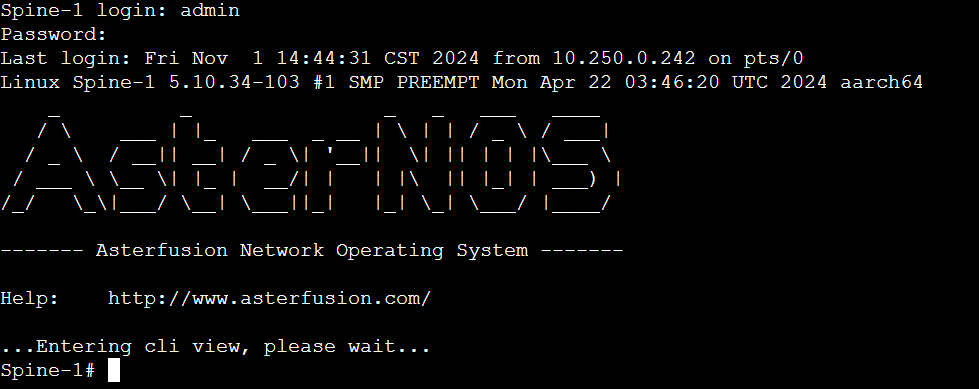
Run the following commands on both devices:
Spine-1# configure terminal
Spine-1(config)# interface ethernet 49
Spine-1(config-if-49)# ip address 172.16.11.34/29
Spine-1(config-if-49)# exit
Spine-1(config)# ip route 0.0.0.0/0 172.16.11.36
Spine-1(config)# ucentral-client server 52.76.134.89
Spine-1(config)# ucentral-client enable
At this point, both spine devices should be online on the controller.
4.3.2 Configure temporary DHCP service to ensure leaf devices are online
There are two ways to configure temporary DHCP service, which are introduced below:
1.Use the serial port configuration to use one of the spine devices as a temporary DHCP server. Here, spine-2 is selected and the configuration is as follows:
Spine-2(config)# interface vlan 4094
Spine-2(config)# port-group ethernet 51-54
Spine-2(config- port-group-51-54)# switchport access vlan 4094
Spine-2(config)# interface vlan 4094
Spine-2(config-vlanif-4094)# ip address 172.16.100.1
Spine-2(config-vlanif-4094)# exit
Spine-2(config)# dhcp pool test
Spine-2(config- dhcp-pool-test)# network 172.16.100.0 255.255.255.0
Spine-2(config- dhcp-pool-test)# address-pool 172.16.100.2 172.16.100.254
Spine-2(config- dhcp-pool-test)# lease-time 7000 10000
Spine-2(config- dhcp-pool-test)# routers 172.16.100.1
Spine-2(config- dhcp-pool-test)# capwap 52.76.134.89
Spine-2(config- dhcp-pool-test)# vlan 4094
Note: The DHCP service here only provides temporary addresses for leaf devices so that leaf devices can access the Internet and discover the controller. After the controller sends the leaf basic configuration, this DHCP service becomes invalid and needs to be manually deleted.
Then configure the routing information of the GW device to ensure that the spine device and leaf devices can access the controller. At this point, both the spine and leaf devices have completed the initial online work.
2.Use the script on the controller to send a temporary DHCP service to one of the spine devices
This method is simpler and more convenient. Find the script option in the left navigation bar of the controller page, as shown below:
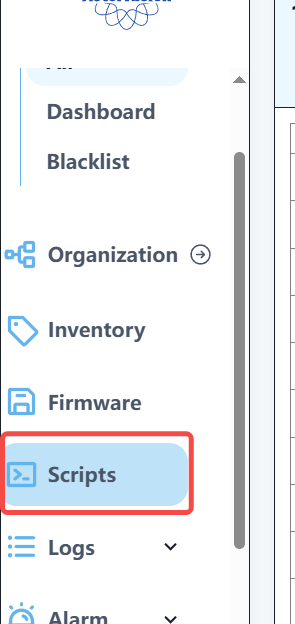
Enter the script options and select Spine DHCP config for Leaf script.
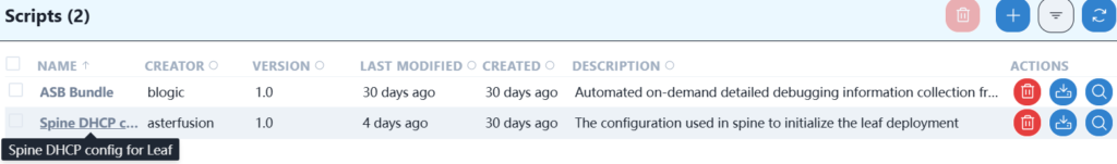
Modify the relevant content of this script.
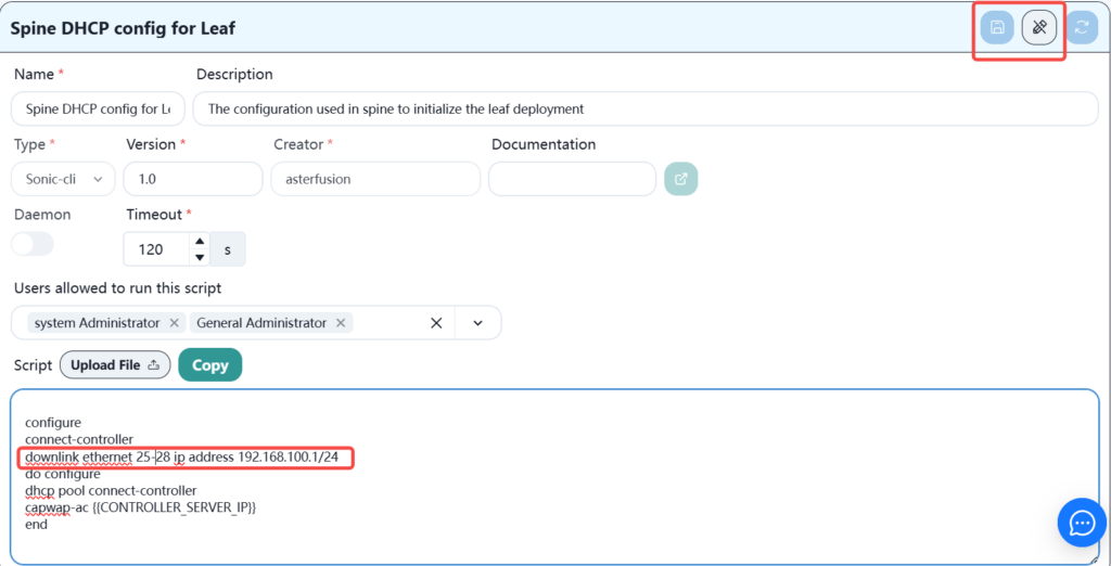
You only need to modify the downstream interface that connects the spine interface to the leaf. The IP address is used temporarily. You can use the default one in the script or modify it yourself. When the leaf device is online, this IP address will become invalid. Click Save after modification.
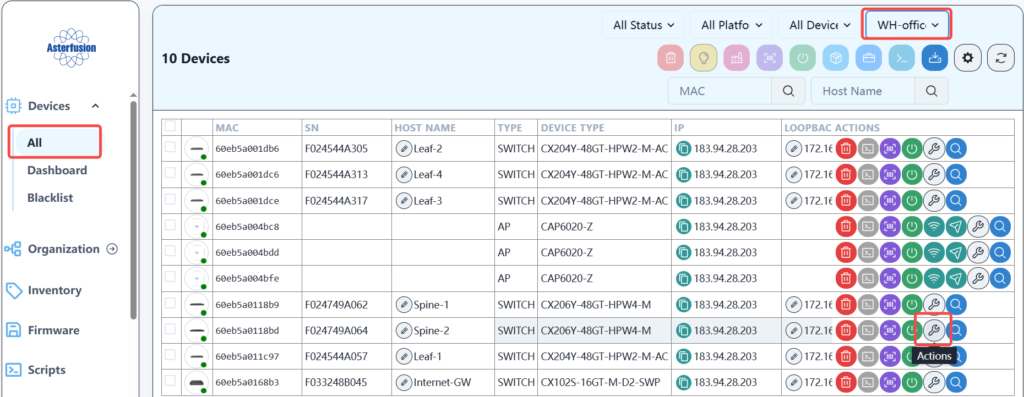
In the device navigation bar, select the corresponding location and device and send the script as follows:
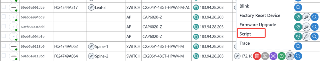
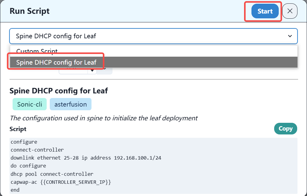
Select the script and run it.
After the leaf device obtains the IP address and configures the relevant routes on the GW device, you can see the leaf device online on the controller.
When the leaf and spine devices are all online, all subsequent deployment operations only need to be completed on the controller.
4.4 Configuring DHCP Server on GW
This deployment deploys the DHCP service on the GW device CX102S.
According to the business plan, three DHCP address pools need to be deployed. The specific configuration is as follows:
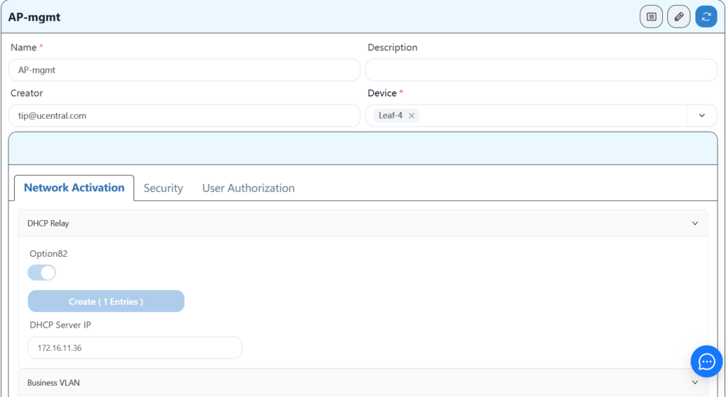
4.4.1 Configure the AP-mgmt address pool
sonic# configure terminal
sonic(config)# dhcp pool AP-mgmt
sonic(config-dhcp-pool-AP-mgmt)# address-pool 172.16.100.2 172.16.100.254
sonic(config-dhcp-pool-AP-mgmt)# dns 8.8.8.8
sonic(config-dhcp-pool-AP-mgmt)# network 172.16.100.0 172.16.100.254
sonic(config-dhcp-pool-AP-mgmt)# routers 172.16.100.1
sonic(config-dhcp-pool-AP-mgmt)# vlan 51
sonic(config-dhcp-pool-AP-mgmt)# capwap-ac 52.76.134.89
4.4.2 Configure the AP-user address pool
sonic# configure terminal
sonic(config)# dhcp pool AP-user
sonic(config-dhcp-pool-AP-user)# address-pool 192.168.22.2 192.168.22.254
sonic(config-dhcp-pool-AP-user)# dns 8.8.8.8
sonic(config-dhcp-pool-AP-user)# option54 192.168.22.1
sonic(config-dhcp-pool-AP-user)# network 192.168.22.0 192.168.22.254
sonic(config-dhcp-pool-AP-user)# routers 192.168.22.1
sonic(config-dhcp-pool-AP-user)# vlan 52
4.4.3 Configuring a Wired User Address Pool
sonic# configure terminal
sonic(config)# dhcp pool Youxian-user
sonic(config-dhcp-pool-Youxian-user)# address-pool 192.168.23.2 192.168.23.254
sonic(config-dhcp-pool-Youxian-user)# dns 8.8.8.8
sonic(config-dhcp-pool-Youxian-user)# network 192.168.23.0 192.168.23.254
sonic(config-dhcp-pool-Youxian-user)# routers 192.168.23.1
sonic(config-dhcp-pool-Youxian-user)# vlan 53
After adding the relevant routes to the above network segments on CX102S, when the terminal device obtains the IP addresses of these network segments, it can access the Internet normally.
Now, you should be able to see that the spine device and leaf device have been successfully online on the controller.
4.5 CX102S switch module configuration
Internet-GW# show running-config
interface ethernet 1
switchport access vlan 101
!
interface ethernet 2
switchport access vlan 102
!
interface ethernet 3
!
interface ethernet 16
!
interface ethernet 17
description to-spine1-ethernet49
link-aggregation-group 1
!
interface ethernet 18
description to-spine2-ethernet49
link-aggregation-group 1
!
interface ethernet 19
switchport trunk vlan 101
switchport trunk vlan 102
switchport trunk vlan 200
!
interface ethernet 20
switchport access vlan 200
!
interface loopback 0
ip address 172.16.1.7/32
!
vlan 1
!
vlan 51
!
vlan 52
!
vlan 53
!
vlan 101
description pppoe
!
vlan 102
description zhuanxian
!
vlan 200
description lan
!
interface vlan 1
ip address 192.168.1.254/24
!
interface vlan 200
dhcp select server
ip address 172.16.11.36/29
!
interface link-aggregation 1
switchport access vlan 200
!
hostname Internet-GW
!
dhcp pool AP-mgmt
address-pool 172.16.100.2 172.16.100.254
capwap-ac 43.192.22.13
dns 218.104.111.111,218.104.111.114
lease-time 6000 12000
network 172.16.100.0 255.255.255.0
routers 172.16.100.1
vlan 51
!
dhcp pool AP-user
address-pool 192.168.22.2 192.168.22.254
dns 218.104.111.111,218.104.111.114
option54 192.168.22.1
lease-time 6000 12000
network 192.168.22.0 255.255.255.0
routers 192.168.22.1
vlan 52
!
dhcp pool Youxian-user
address-pool 192.168.23.2 192.168.23.254
dns 218.104.111.111,218.104.111.114
lease-time 6000 12000
network 192.168.23.0 255.255.255.0
routers 192.168.23.1
vlan 53
!
lldp enable
!
mac-address static 00:11:22:33:44:02 vlan 200 ethernet 20
!
mirror session 1 span src-ethernet 19 dst-ethernet 20
!
ucentral-client enable
!
ucentral-client server 43.192.22.13
!
ip route 192.168.22.0/24 172.16.11.33
ip route 192.168.23.0/24 172.16.11.33
ip route 172.16.1.0/28 172.16.11.33
ip route 43.192.22.13/32 172.16.11.34
!
end
4.6 CX102S device DPU1 openwrt configuration
The following figure shows the interface established on openwrt:
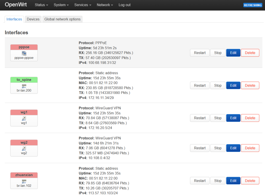
Among them, zhuanxian and pppoe are external network interfaces, to_spine is the internal network interface, wg1 is the VPN dedicated line interface leading to PA private cloud, and wg2 is the VPN dedicated line interface leading to AWS public cloud.
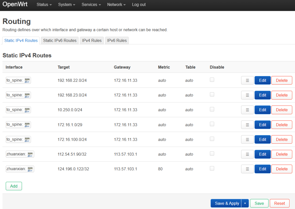
The figure below is the routing information:
4.7 Basic network configuration delivery
Distribute the previously saved basic configurations of each device.
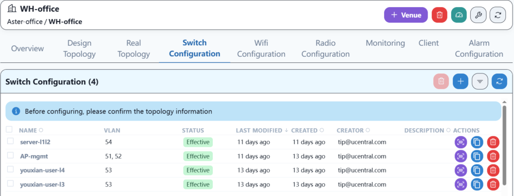
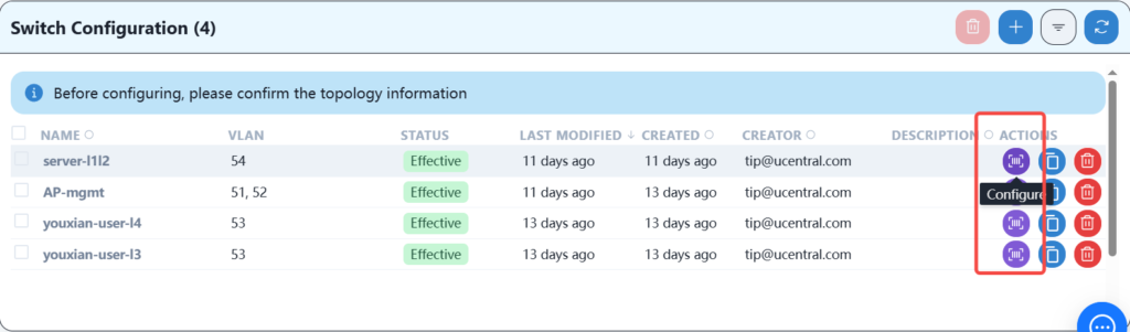
4.8 Wired service configuration and distribution
Configure wired services according to the plan.
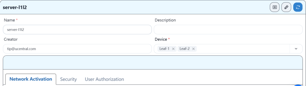
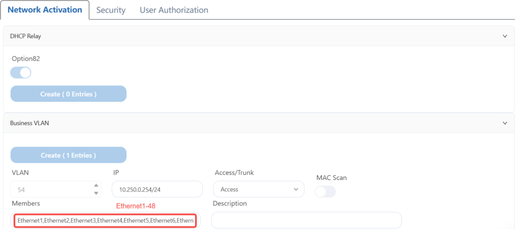
4.8.1 Configure wired server services
4.8.2 Configuring AP Services
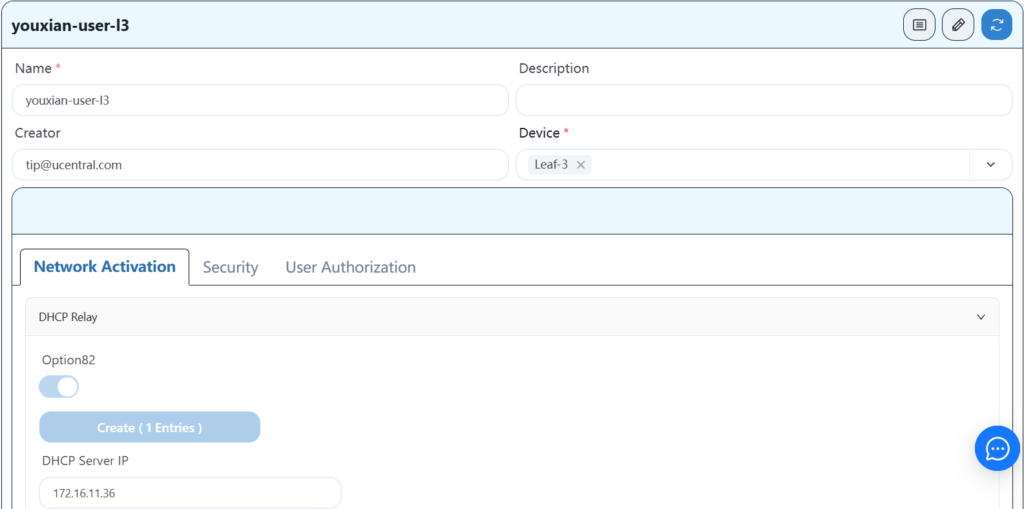
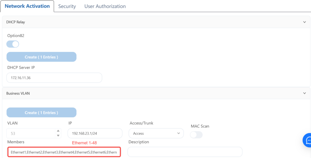
4.8.3 Configuring Leaf-3 Wired User Services
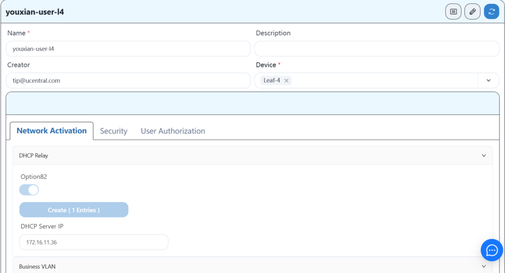
4.8.4 Configuring Leaf-4 Wired User Services

4.8.5 Send configuration
After configuring the wired service, the AP should be able to obtain its own management IP address, and you should be able to see three APs online on the controller. After the APs are online, you can configure the wireless service.
4.9 Wi-Fi service configuration delivery
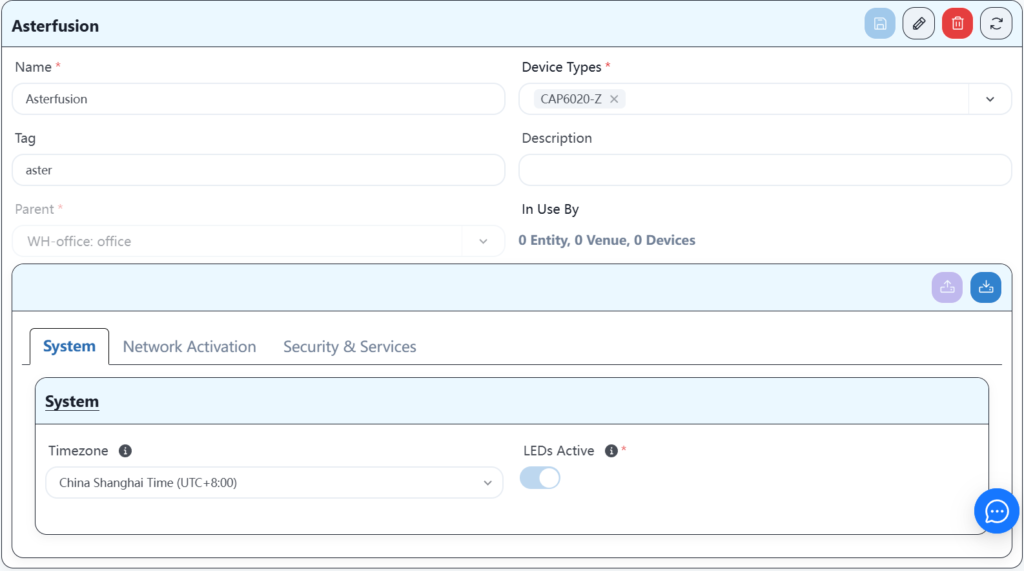
create a wireless service configuration template.
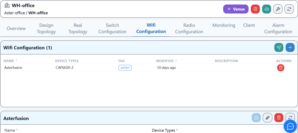
Configure basic WI-FI information.
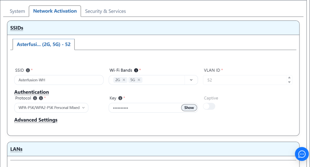
Configure Wi-Fi service information.
After completing the service template configuration and saving, click Push Service.
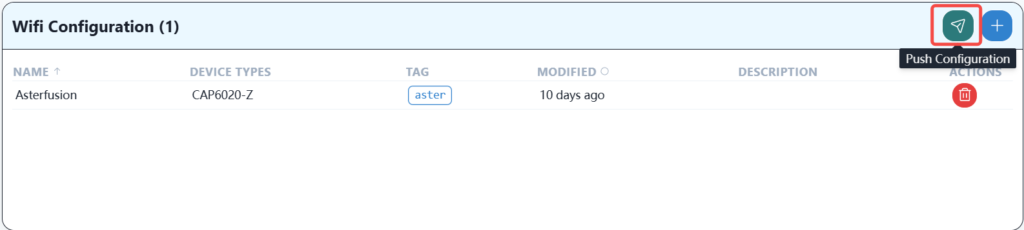
When you see that the push is successful, it means that the wireless service has been successfully delivered and the wireless terminal can connect to and use this network.
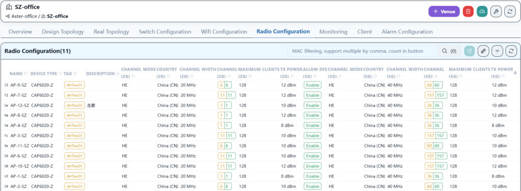
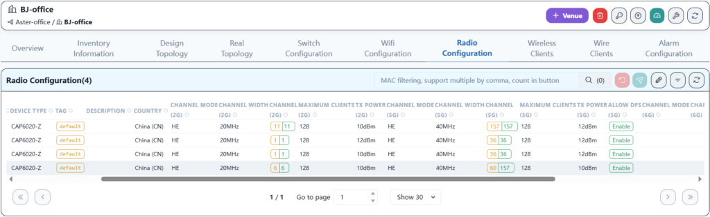
4.10 RF parameter configuration delivery
The RF parameters can use the default configuration, or you can manually adjust parameters such as channel and transmit power.
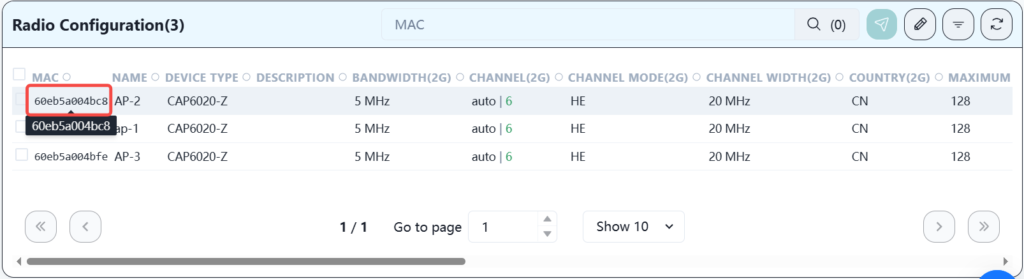
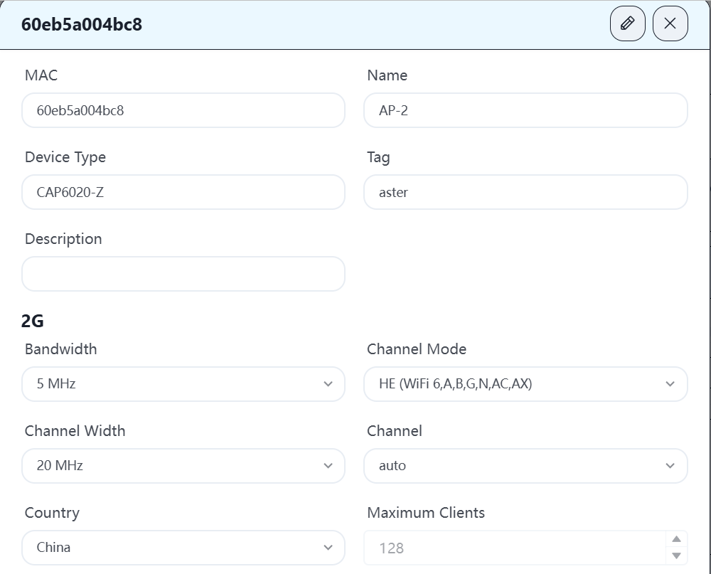
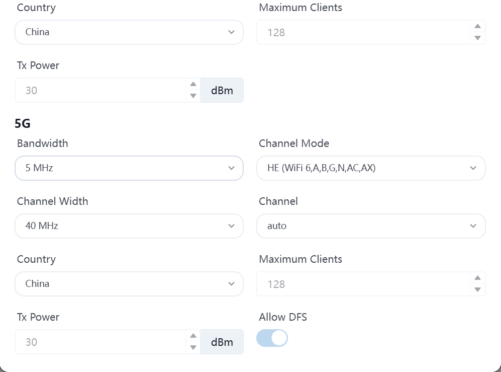
Click on the mac address of each AP to enter this device to modify the corresponding parameters. In order to have a better network experience, it is recommended to manually adjust the channel, assign adjacent APs to different channels, and adjust the transmission strategy according to the distance between APs to reduce signal interference between APs.
4.11 WH user terminal is online
4.11.1 Connecting a wired user terminal to the network
According to the plan, the network cable of the wired user terminal is plugged into the 1-48 interface of leaf3 and the 4-48 interface of leaf4, so that the correct IP address can be obtained and the Internet can be accessed.
4.11.2 Connecting wireless terminals to the network
By connecting wireless terminals such as laptops, mobile phones, wireless large screens, printers, etc. to Wi-Fi, you can obtain the correct IP address and access the Internet.
4.11.3 Connect the wired server to the network
According to the plan, connect the network cable of the wired server terminal to the 1-48 interface of leaf1 and leaf2, and configure the correct IP address to access the Internet.
4.11.4 Inter-service access between terminals in each intranet segment
- Use a laptop to ssh to access the wired PC device, and they can communicate with each other. Wireless terminal to wired terminal.
- Use the laptop to ssh to access the wired server device, and they can communicate with each other. Wireless terminal to wired server.
- Use a wired PC to access the wired server device, and they can communicate with each other. Wired terminal to wired server.
- Use PC device to access printer terminal and print files normally. Wireless terminal accesses special terminal.
At this point, the entire network has been deployed.
5 Incorporate SZ office network into controller management
This chapter mainly introduces the operation process of incorporating the SZ office network into the app.cloudswitch.io controller management. Since the original SZ network was deployed using the company’s CX-M series products and has been planned and adjusted to a full three-layer network architecture, it is currently managed and maintained by a local controller. Now all services need to be migrated to the new controller.
5.1 Basic information of SZ office network
The device information is shown in the following table:
| Model | Role | Quantity | Version | Note |
|---|---|---|---|---|
| CX308P-48Y-M | Spine | 2 | V5.2R009P01 | |
| CX204Y-48GT-M-AC | Leaf | 5 | V5.2R009P02 | |
| CX204Y-48GT-HPW2-M-AC | Leaf | 1 | V5.2R009P02 | |
| CX204Y-24GT-M-SWP2 | Leaf | 1 | V5.2R009P02 | |
| CAP6020-Z | AP | 11 | Tip-devel-cc97016c | |
| Aster-Fabric-Controller | Controller | 1 | V1.0R005T01 |
Topology

The current device version needs to be upgraded to be compatible with the new controller version.
5.2 Switch device version upgrade
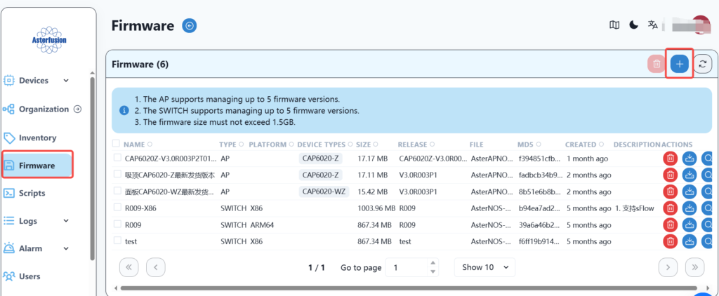
5.2.1 Upload the version to the controller
In order to better match the new controller, we need to upgrade the switch device. First, upload the version, find the firmware menu on the SZ local controller, and then select Add a new version image.
Fill in the relevant information, select the image file, and save it.
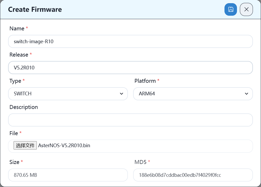
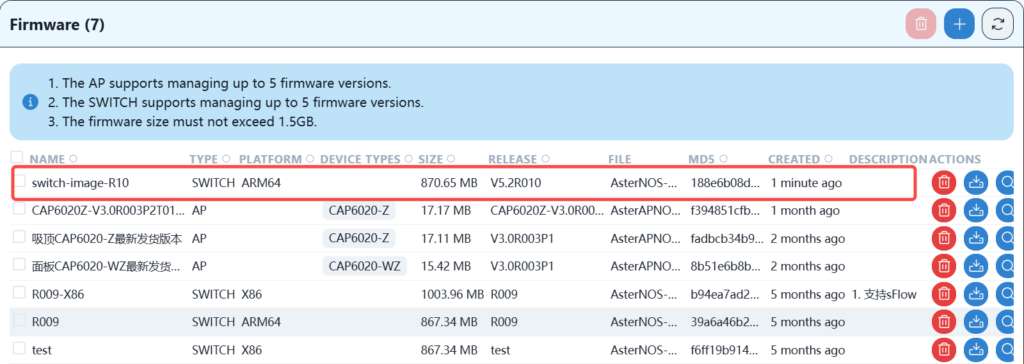
After the upload is successful, you can see the new version image in the list.
5.2.2 Device version upgrade
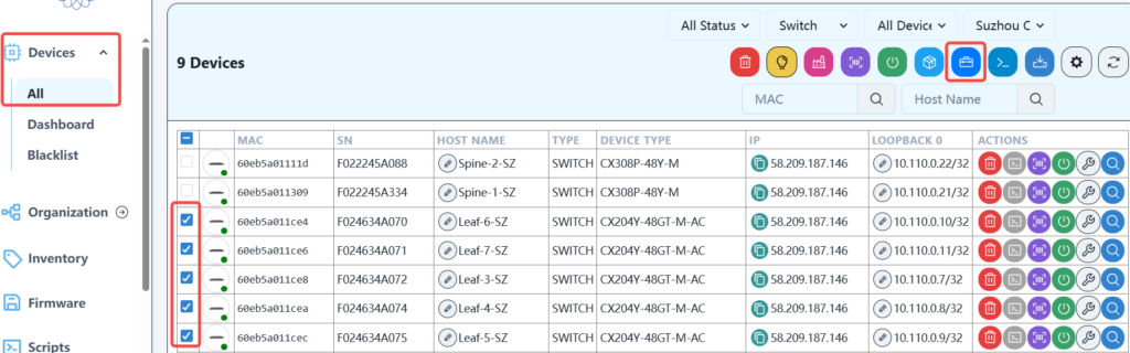
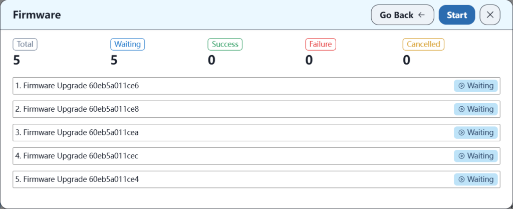
Find the device column on the controller, check the device to be upgraded, and then click the Firmware Upgrade button.
Then select the firmware version and click next.
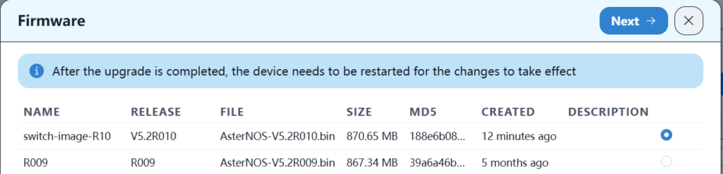
Then click Start Upgrade. After the upgrade is complete, you need to restart for it to take effect.
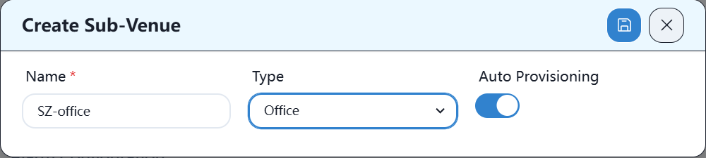
5.3 Create the corresponding office space on the new controller
Under the organization corresponding to the controller, create a new place as follows:

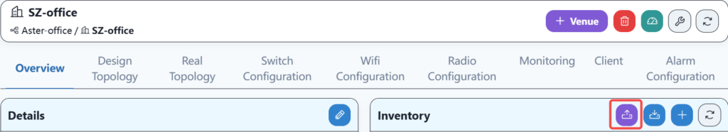
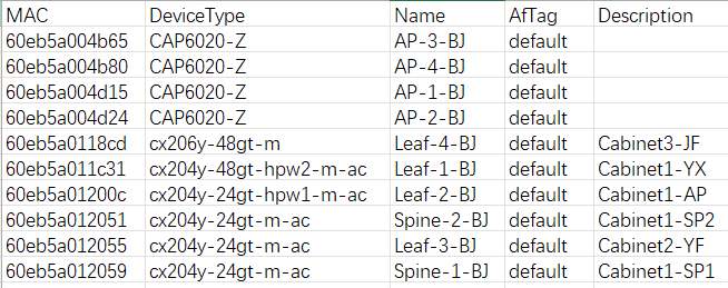
5.4 Import device information into the new controller
Enter the SZ-office location and import the equipment information into the warehouse.
Then select the device information file and test uploading. If the format is correct, the uploading is completed.
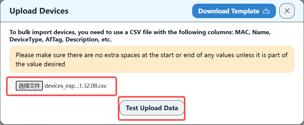
The format of the device information file is as follows:
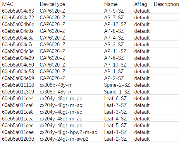
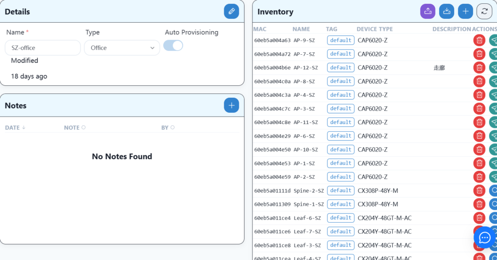
After the import is completed, you can see the relevant equipment information in the warehouse of SZ-office.
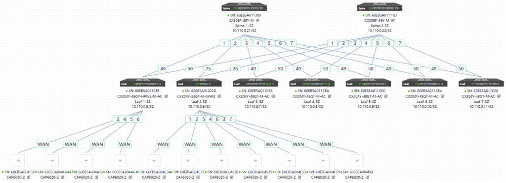
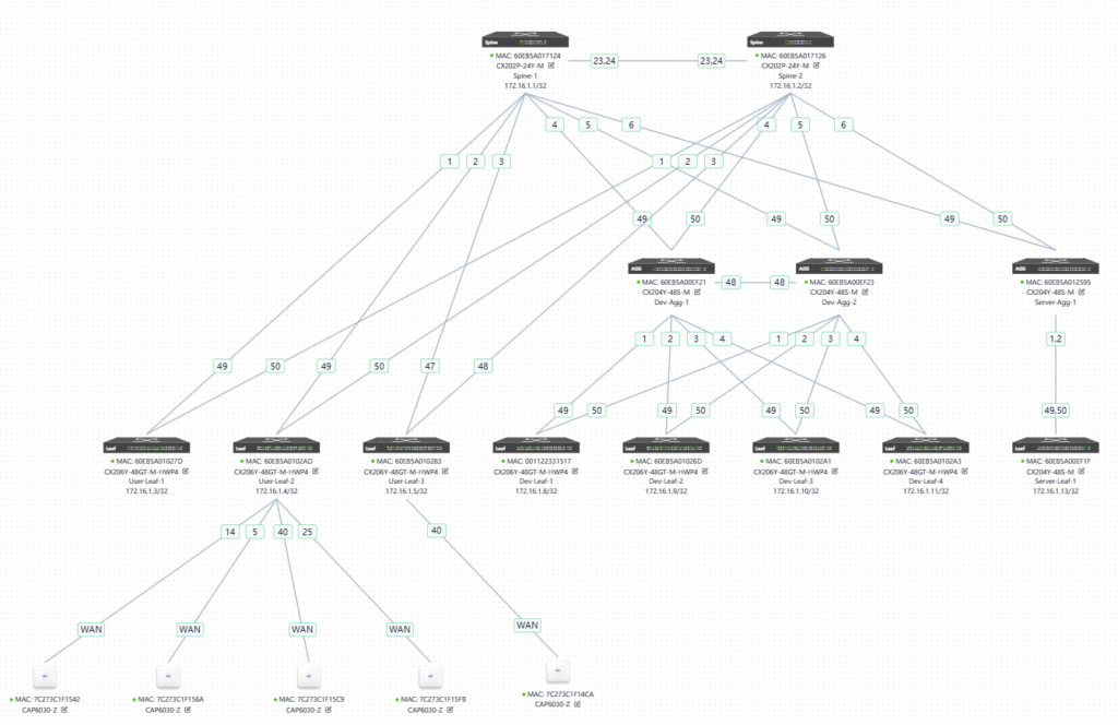
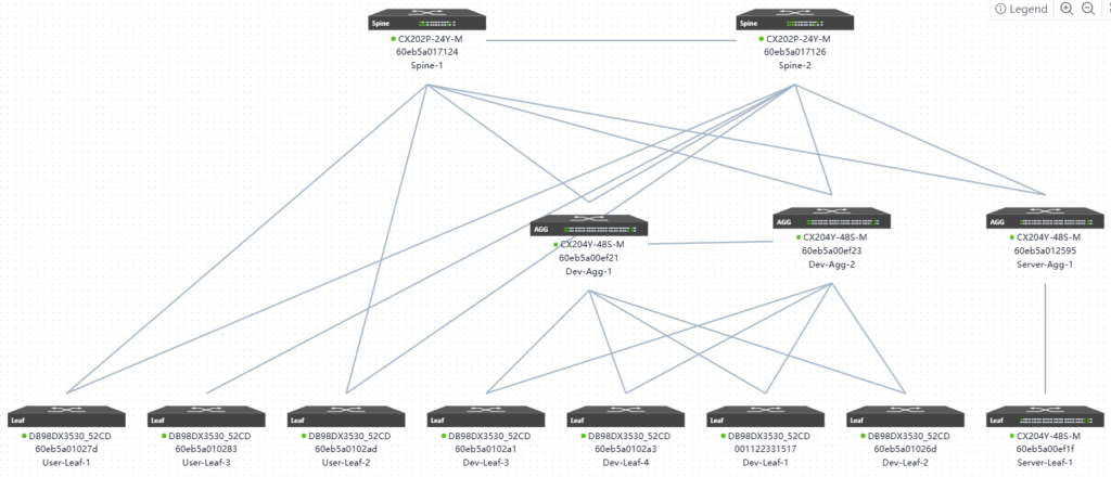
5.5 Network planning based on existing network topology information
The network topology planned here is consistent with the original topology, as shown below:
5.6 Create a new service configuration on the new controller
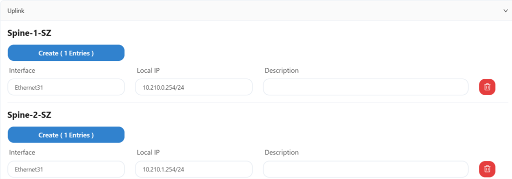
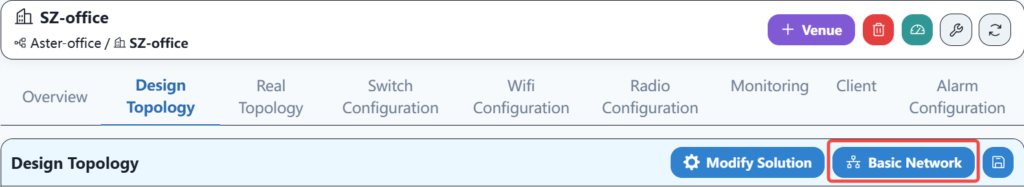
5.6.1 Basic network configuration
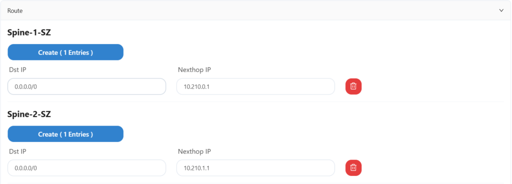
The sz office network does not use HA, and the uplink information and routing configuration are as follows:
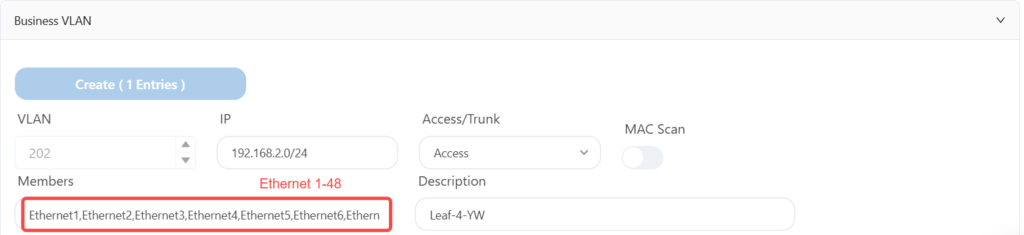
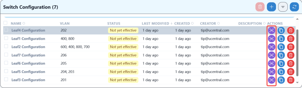
5.6.2 Wired service configuration
The specific services are as follows:
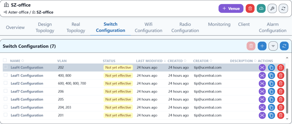
The leaf1 configuration is as follows:

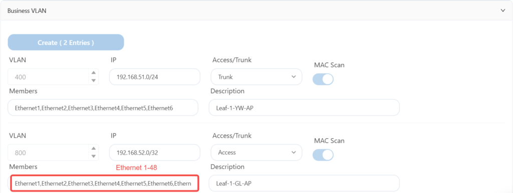
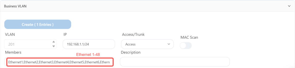
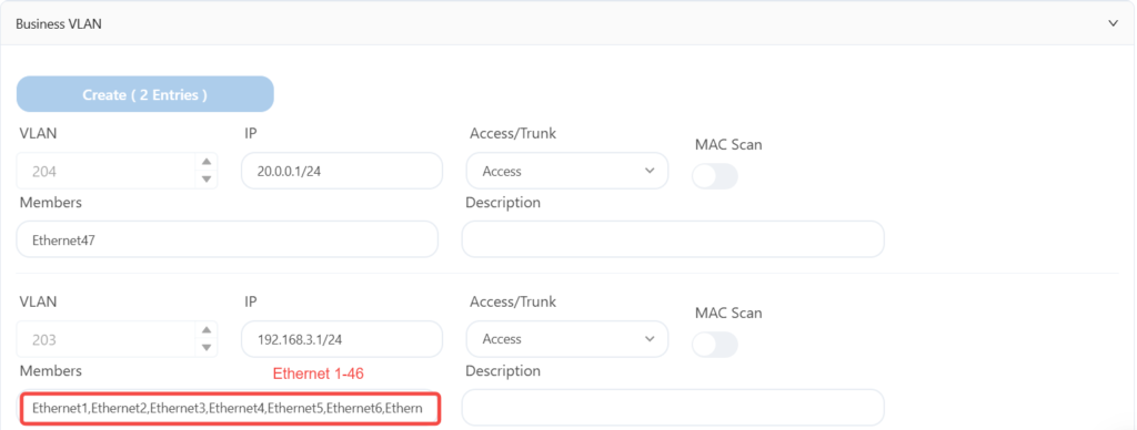
Since the DHCP relay configuration is the same for each leaf, leaf2-7 only displays business VLAN information.
The leaf2 configuration is as follows:

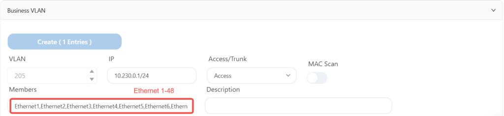
The leaf3 is configured as follows:
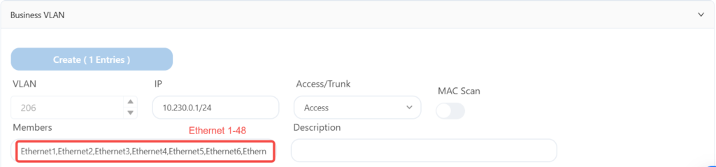
The leaf4 is configured as follows:
The leaf5 is configured as follows:
The leaf6 is configured as follows:
The leaf7 is configured as follows:
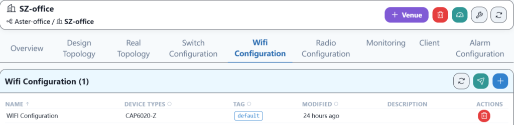
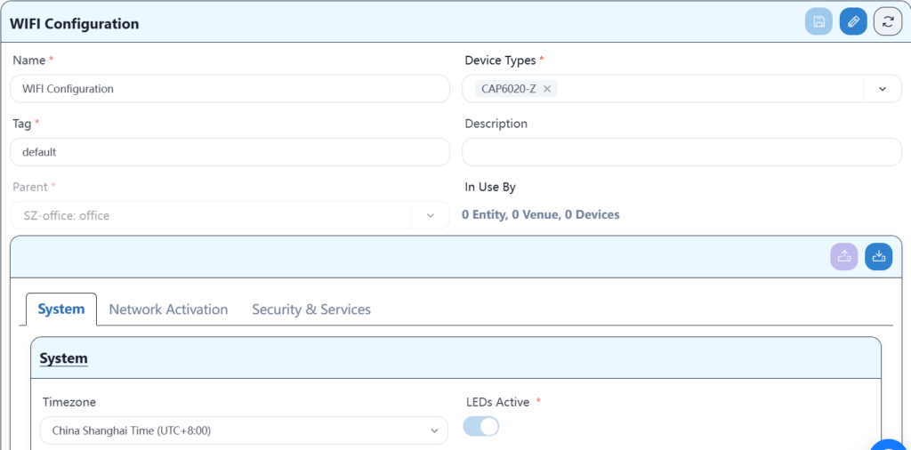
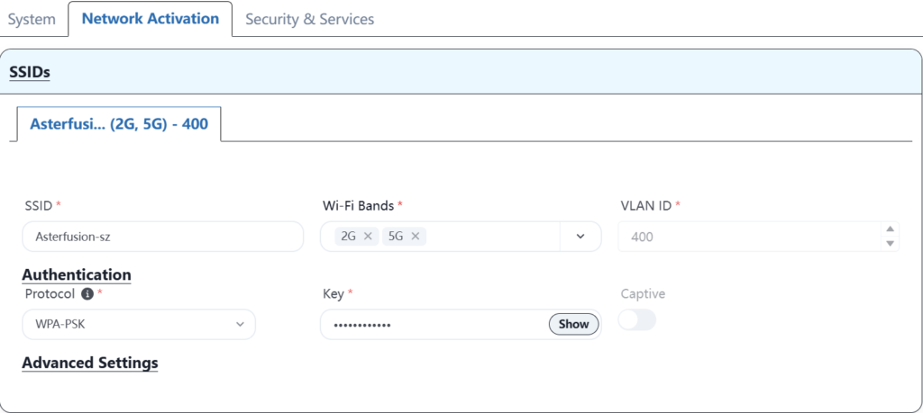
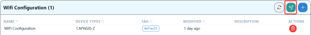
5.6.3 Wi-Fi service configuration
The Wi-Fi service configuration is as follows:
5.7 Device goes online on the new controller
Log in to each device via the serial port or SSH, modify the controller IP address of each switch device, and then go online with the new controller. The specific command to modify the IP address is as follows:
Leaf-1# configure terminal
Leaf-1(config)# ucentral-client server 52.76.134.89
5.8 Device configuration delivery
5.8.1 Basic network configuration delivery
Distribute the saved basic network configuration.
5.8.2 Wired service configuration delivery
Send the created configuration to the device.
After configuring the wired service, the AP should be able to obtain its own management IP address, and you should be able to see three APs online on the controller. After the APs are online, you can configure the wireless service.
5.8.3 Wi-Fi service configuration delivery
Send the created configuration to the AP.
After the download is successful, the wireless terminal should be able to reconnect and access the Internet.
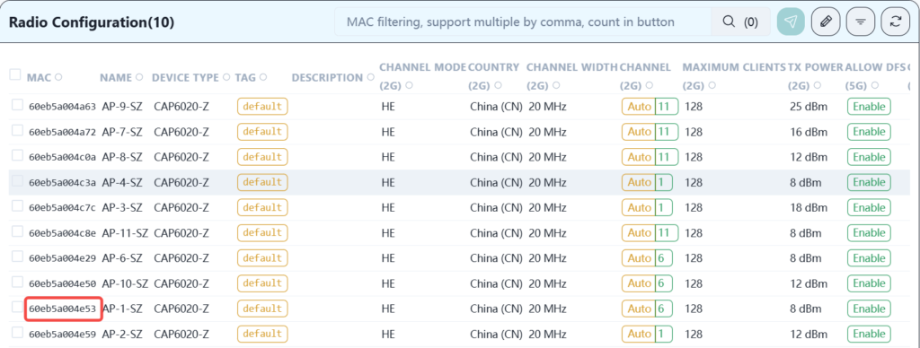
5.8.4 RF parameter configuration delivery
According to the signal strength and mutual interference, the RF transmission power can be adjusted appropriately to reduce signal interference. Taking AP-1 as an example, the modification operation is shown in the figure below:
Click the corresponding mac address to enter the setting page.
Modify related parameters.
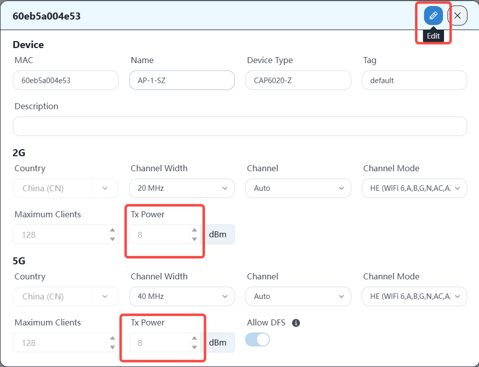
After adjusting each AP, the configuration is as follows:
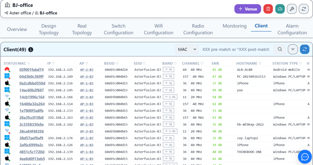
5.9 Verification test
After all configurations are correctly issued, the entire network configuration is online. At this time, wired services and wireless services should be able to communicate normally and access the Internet.
- Wired PC service test
The wired PC terminal in the office can obtain the IP address and can access the Internet normally. - Wired server service test
The server in the R&D area can access the Internet normally after configuring the correct IP address. - Wireless terminal service test
Mobile phones and laptop terminals can connect to Wi-Fi normally and access the Internet normally.
6 BJ Office network Implementation
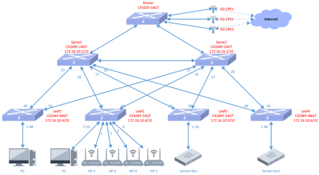
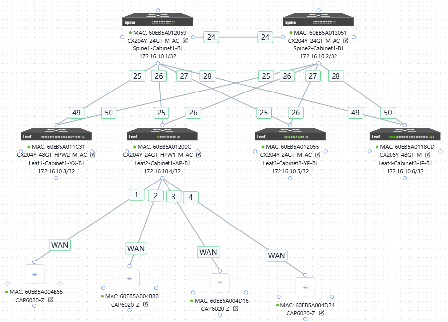
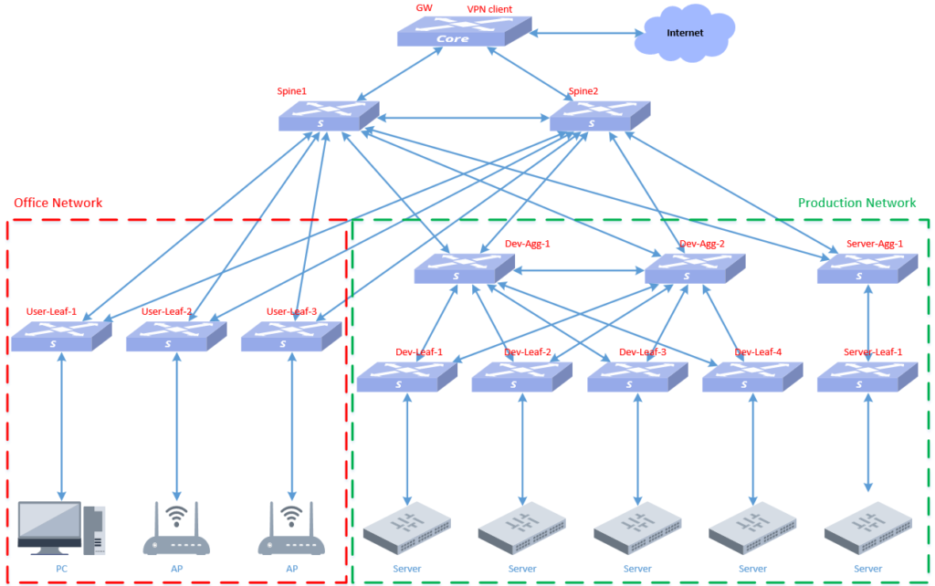
6.1 Topology planning
The network outlet of BJ Park is different from the other three places. It uses 5G wireless routing to access the Internet. The intranet still uses the spin+leaf architecture, as shown belows:
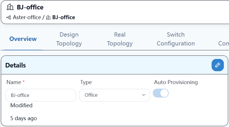
6.2 Create an office space on the controller
6.3 Importing equipment into controller
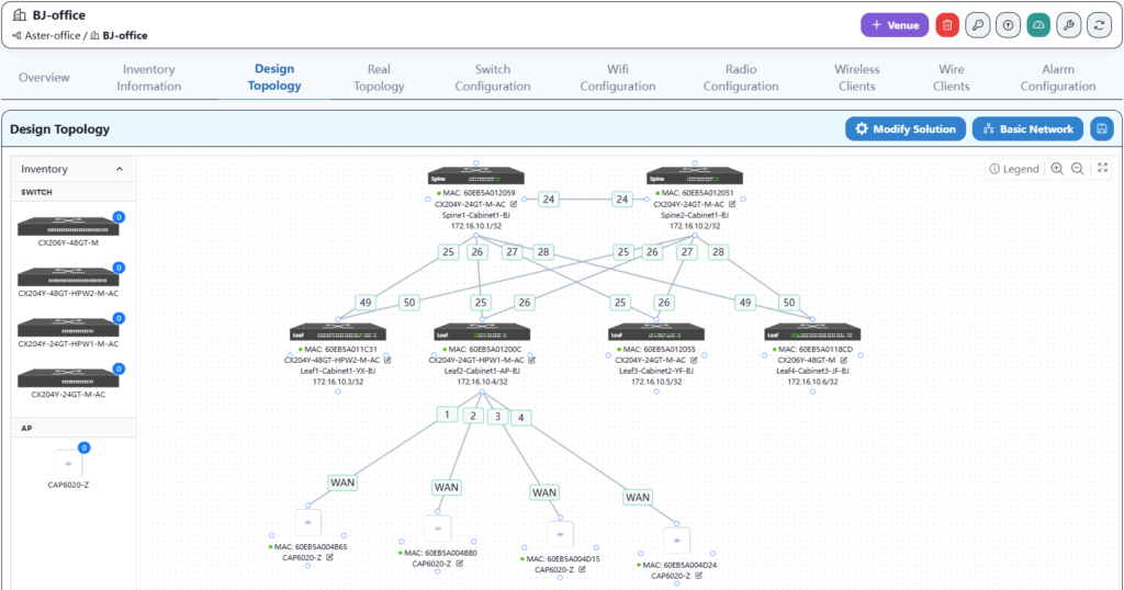
6.4 Create a topology on the controller
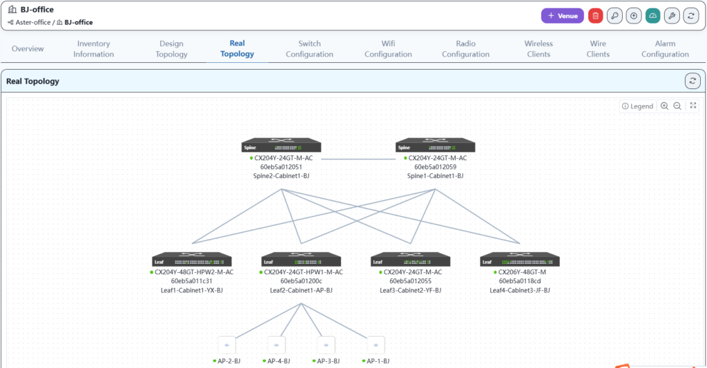
6.5 Device online
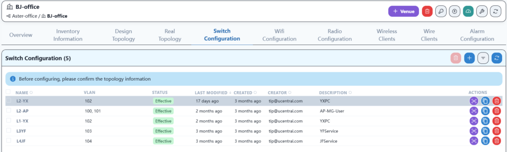
The steps for equipment online and business configuration are the same as those for wh office online, so I will not describe them one by one.
The final result is as follows:
Here, the channels and power are optimized according to the AP locations in the office to ensure that the Wi-Fi signal remains stable in any corner of the office.
7 XA Office network implementation
7.1 Topology planning
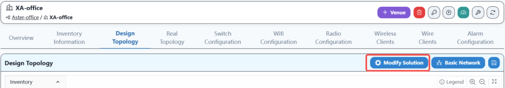
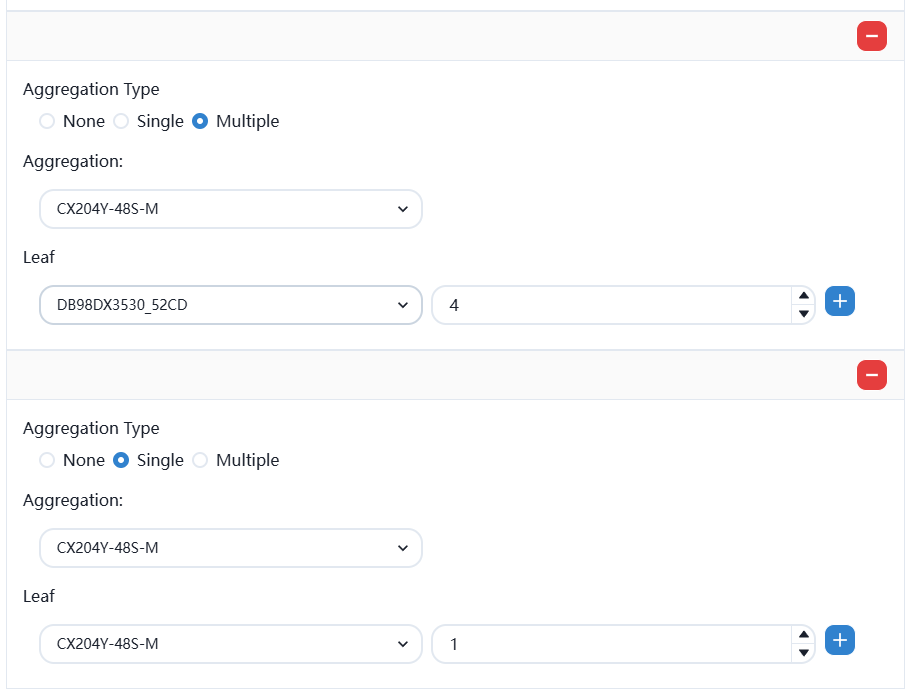
Since the XA campus network has special production requirements, we planned the XA campus network as a hybrid scenario networking architecture of spine+leaf and mc-lag in the first planning chapter. As follows:
7.2 Create an office space on the controller
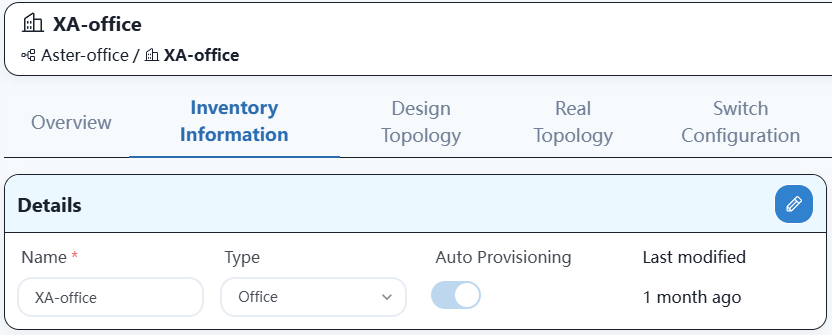
7.3 Importing equipment into controller
The equipment import process is the same as that of other office locations and will not be elaborated on here.
7.4 Basic network configuration delivery
This is a mixed scenario network, which is different from the other three locations. The configuration is as follows:
After saving, enter the basic network configuration.
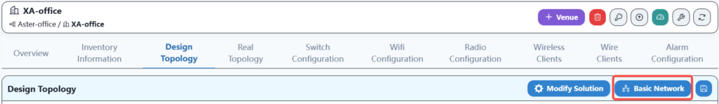
Configure as follow:
Complete the configuration and save.
7.5 Create a topology on the controller
After the topology is established, you can prepare for online work.
7.6 Device online
The steps for device online and business configuration are the same as those for WH office online, so they will not be described one by one.
7.7 Actual topology after going online
7.8 Network Delivery
The method of issuing wired and wireless services is the same as other campus, so it will not be described one by one.
7.9 Network Verification
When all configurations are correctly delivered, the entire network configuration is online. At this point, wired and wireless services should be able to communicate normally and access the internet.
1.Wired PC service test
The wired PC terminal in the office can obtain the IP address and access the Internet normally.
2.Wired server service test
The server in the R&D area can access the Internet normally after the correct IP address is configured.
3.Wireless terminal service test
Mobile phones and laptop terminals can connect to WiFi normally and access the Internet normally.
Asterfusion CX-N & CX-M SONiC switches as the links below
CX-N series switches
CX-M series switches
If you have more technical questions, feel free to propose a ticket on our
https://help.cloudswit.ch/portal/en/signin