Asterfusion Campus network implementation – Part One Master Plan
1 Purpose
In order to introduce the method of deploying the entire campus network using Asterusion CX-M series products and controller products, we have written a series of documents including planning, installation, implementation, and testing acceptance. By reading these documents, users can easily and quickly plan and deploy the campus network online. Once the user has already planned the overall network and prepared for the launch, they can deploy the entire network online within 30 minutes. This article is the first part: overall planning; which mainly elaborates on how to plan a company network with 4 R&D centers based on our actual deployment experience, to meet the needs of network interconnection and resource sharing among the centers.
2 Project background
Asterfusion currently has 4 R&D centers located in different cities. As the company’s business expands, the network demands of each R&D center are also gradually increasing. In order to meet the network needs of various departments of the company, it was decided to re-plan and build the company’s overall network.
3 Overall demand
- The company has four major R&D centers, located in four cities: sz, wh, bj and xa, and has two major cloud platform resource pools: PA private cloud and AWS public cloud. R&D centers in various places need to access cloud resources and server resources in other cities at any time.
- Each R&D center must access server resources at high speed, reduce broadcast messages, and ensure network stability.
- Each R&D center must access the server resources of other R&D centers in order to share resources, improve R&D efficiency, and reduce R&D costs.
- The company requires unified planning, construction, management and operation of the entire network in order to maintain network security and stability and make mutual visits between departments more convenient.
- In order to make network maintenance more convenient, the network traffic of each R&D center is required to be visualized.
4 Requirements analysis
- For requirement 1, VPN technology can be used to interconnect the R&D centers and cloud resources in the four places. Therefore, the company’s CX102S product is selected as the routing gateway at the exit gateway position of each R&D center. In addition to the basic switching module, CX102S also has two DPUs. Openwrt is run on DPU1 as the exit route, and the wireguard component is integrated, making it easy to build a VPN. network.
- In order to meet the needs of high-speed bandwidth and reduction of broadcast messages within each R&D center, the whole network three-layer architecture of spine+leaf can be deployed, and distributed gateways can be used. Each network device can be interconnected using 10G/40G/100G high-speed interfaces. , thereby ensuring the intranet bandwidth.
- The needs of each R&D center to access server resources can be solved through VPN technology.
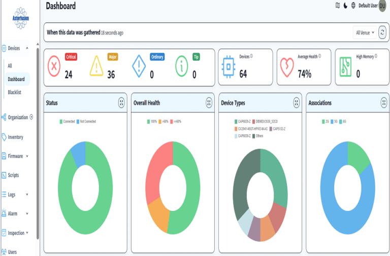
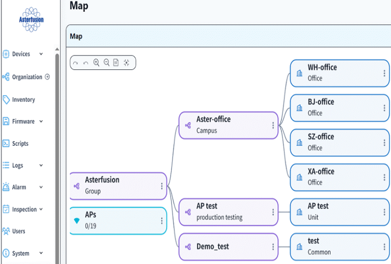
- This network construction uses controllers for unified deployment, so that all networks in various places are displayed on the controller, which facilitates operation, maintenance and management.
- The network traffic visualization of each R&D center is realized by running the ntopng open source software on the DPU2 of the export device CX102S.
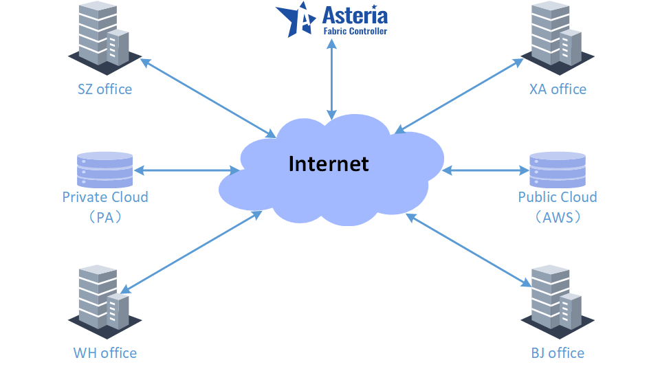
5 Schematic diagram of the company’s overall network
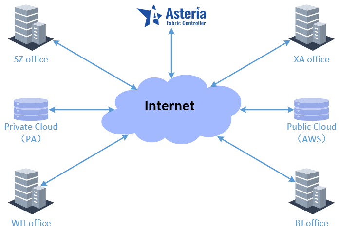
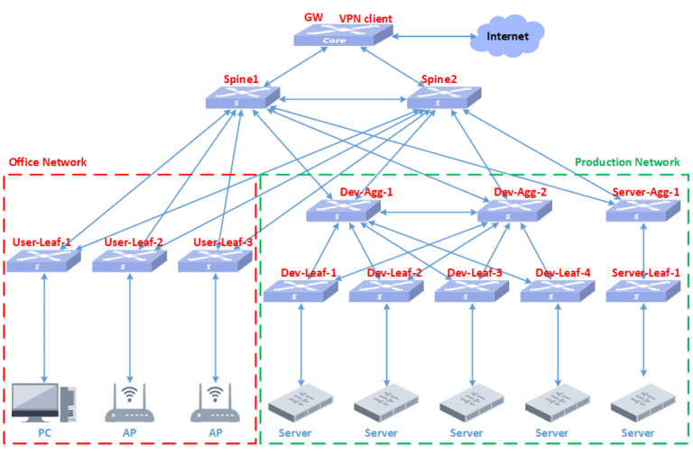
Based on the overall needs of the project, the overall network is planned as shown in the figure above, in which the controller is installed on the public cloud so that administrators can view the network status anytime and anywhere.
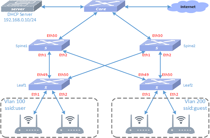
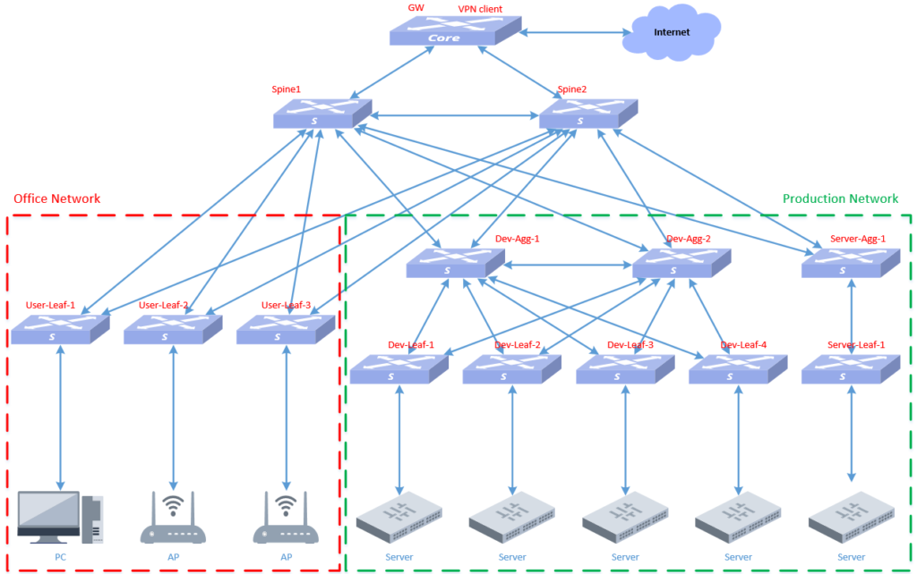
6 Internal network architecture planning of each R&D center
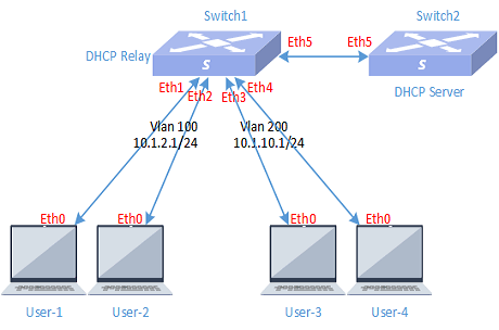
The three R&D centers of SZ WH BJ adopt a spine+leaf architecture for networking, and the specific number of spine, leaf, and AP devices is determined based on the number of personnel, R&D servers, and office space in each region. The internal network is a three-layer network, deployed using distributed gateway, dhcp replay, arp replay, arp to host and other technologies. CX102S intelligent gateway device is uniformly used for network export.
The network architecture diagram is as follows:
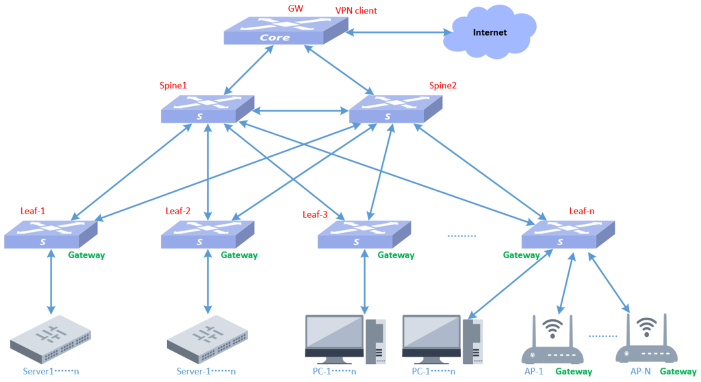
Due to special requirements, the XA R&D center network adopts a hybrid scenario networking architecture of spine+leaf and MC-LAG. As shown in the following figure:
7 Schematic diagram of cloud access traffic of each R&D center
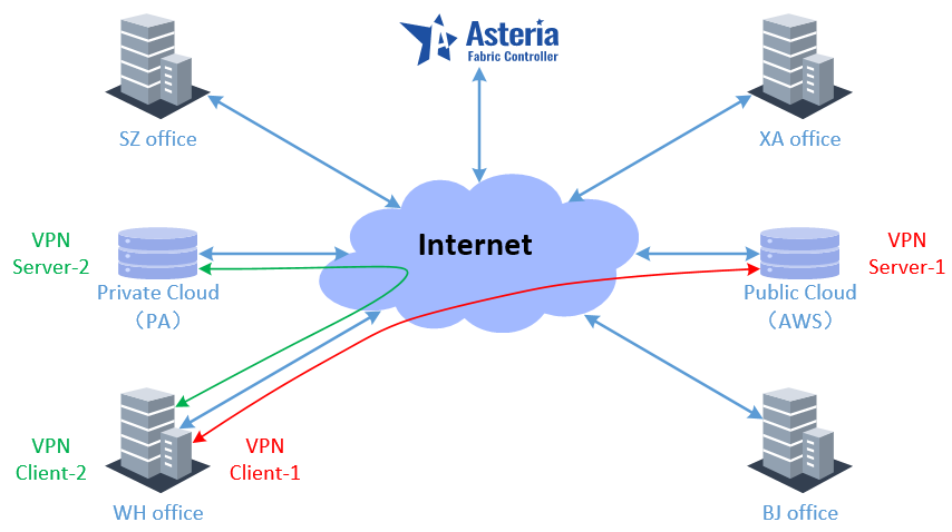
Taking WH office as an example, when R&D centers in various places access the cloud platform as shown in the figure above, they open two VPN clients at the exit of the company’s campus network and connect to the servers of the two cloud platforms respectively.
8 Schematic diagram of mutual visits between R&D centers
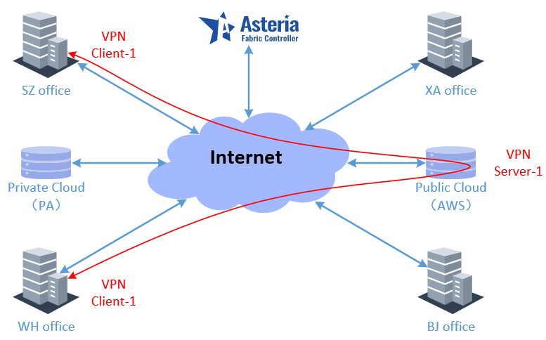
Taking the mutual access between WH office and SZ office as an example, the VPN server of the public cloud is used as the interconnection node in various places, and mutual access can be achieved by simply adding the network segment route of the local intranet to the VPN server.
The above is the overall plan for the company’s network, and we will gradually implement the deployment of networks in various regions according to this plan.
Asterfusion CX-N & CX-M SONiC switches as the links below
CX-N series switches
CX-M series switches
If you have more technical questions, feel free to propose a ticket on our
https://help.cloudswit.ch/portal/en/signin