Asterfusion Campus network implementation – Part Four Verification and operation
1 Purpose
In order to introduce the method of using Asterfusion CX-M series products and controller products to implement the whole network deployment of the campus network, we have compiled a series of documents such as campus network planning, installation, implementation, and test acceptance. By reading these documents, users can quickly and easily implement the planning and deployment of the campus network. When users have planned the entire network and made preparations before going online, users can deploy the entire network and go online within 30 minutes. This article is the fourth part: test acceptance and operation and maintenance; it mainly describes the acceptance test work after the network implementation is completed to see whether it meets the design standards, and introduces the operation and maintenance work of the entire network.
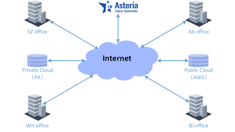
2 Introduction to Asterfusion Network
According to the overall network planning, we have completed the construction of the entire Asterfusion campus network. The following is an introduction to the overall network situation.
2.1 Schematic diagram of the entire network
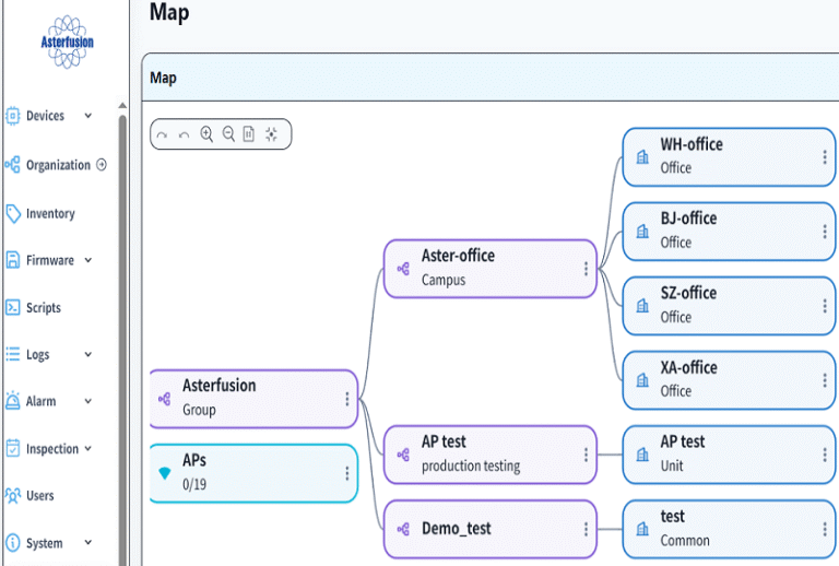
You can view the entire network diagram from the controller. Click the map button in the upper right corner to display the following:
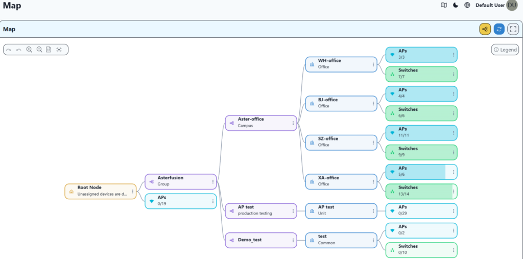
The map allows you to intuitively view the current online status of the device.
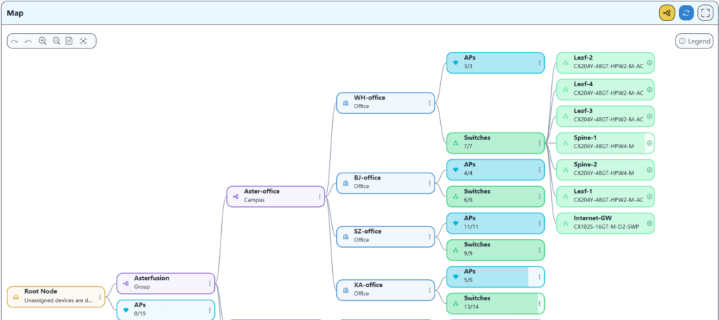
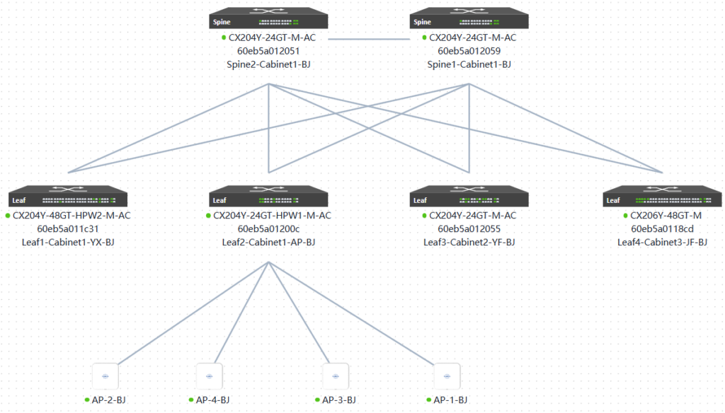
2.2 Real topology of each office
Through the organization menu in the left navigation bar, you can quickly view the actual topology of each office. Take BJ office as an example, as follows:
3 Network Acceptance Test
3.1 Wi-Fi roaming test under the same Leaf
Connect the phone to the network near AP-1, then move it to the network near AP-2, and continue to ping external websites. And observe whether the network is disconnected when the device switches to AP-2.
The traffic path of this test is as follows:
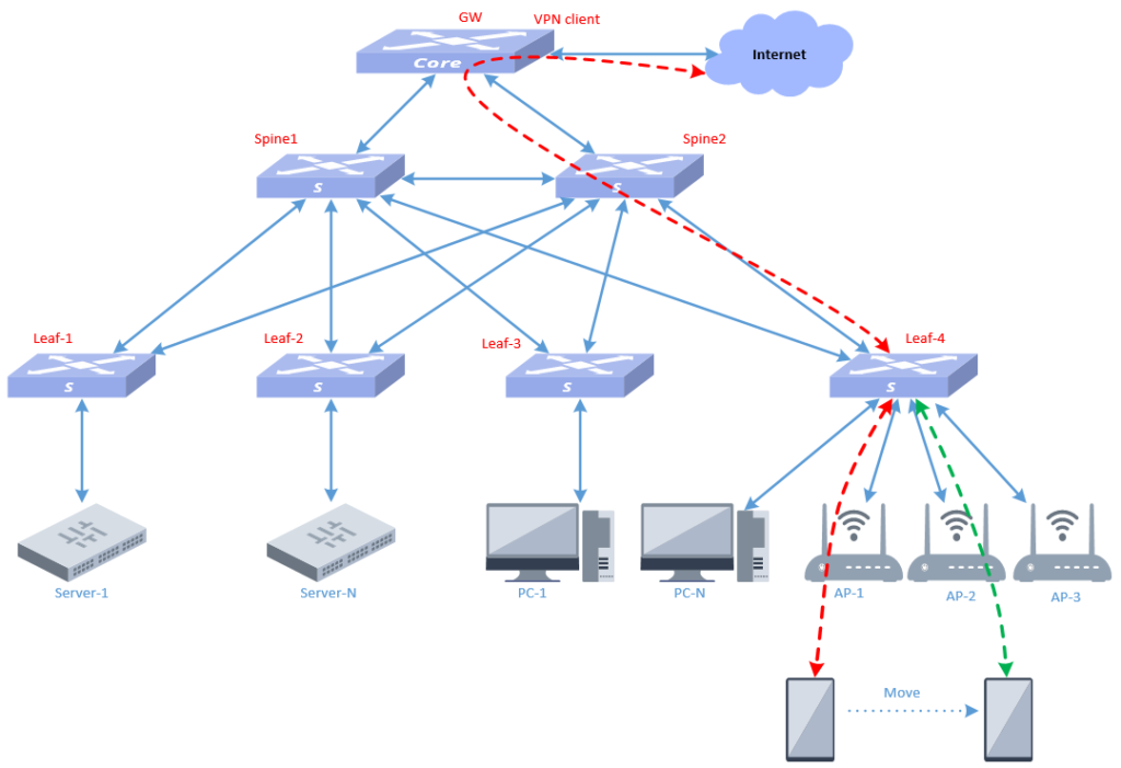
The mobile terminal accesses from AP-1, and the traffic is shown in red. When AP switching occurs, the path for the mobile terminal traffic to reach the leaf switches to green.
This test was conducted in BJ office and tested using the cloudcampus app. The test screenshots are as follows:
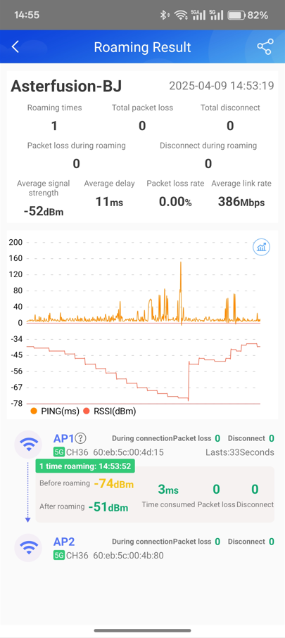
From the above results, we can see that the roaming switching time is 3ms, and there is 0 packet loss and 0 disconnection during roaming switching.
After multiple subsequent tests, when switching occurs, there is 0 packet loss and 0 disconnection, indicating that the network is relatively stable when roaming occurs.
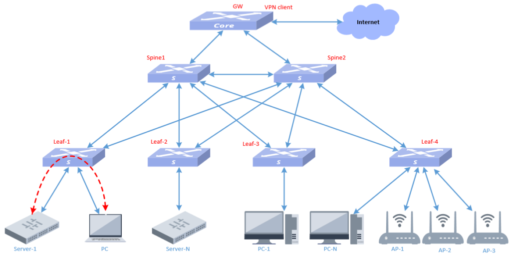
3.2 Wi-Fi roaming test between different Leafs
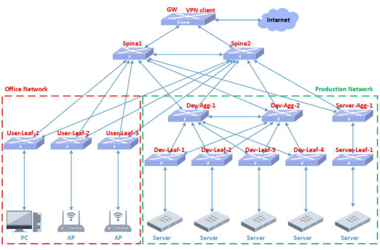
The test topology is shown in the following figure:
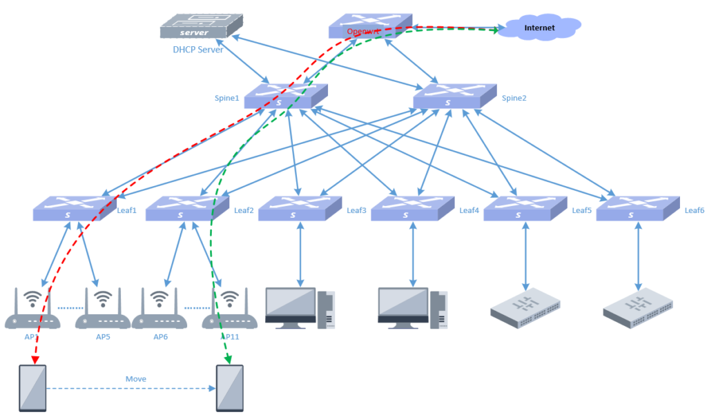
The mobile phone terminal starts to access the network from AP1, and then keeps moving, passing through AP2, AP3 and other APs. The mobile phone data traffic path changes from the red dotted line to the green dotted line, and during this period it crosses from Leaf1 device to Leaf2 device. This test was conducted in the SZ office, and the test results are as follows:
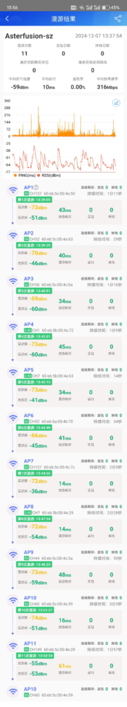
From the above results, we can see that the mobile terminal continues to roam between various APs during movement, but the network is never disconnected and no data packets are lost. The roaming switching time is about milliseconds in time, which is relatively stable.
3.3 Test of file transfer rate between wired terminal devices in the same leaf
Connect a laptop to leaf1, upload a file to the server under leaf1, and check the transmission rate.
The traffic path of this test is as follows:
As shown in the figure above, the red dotted line indicates the traffic path.
This test uses the Xterm tool under the Windows system for transmission testing. The test screenshots are as follows:
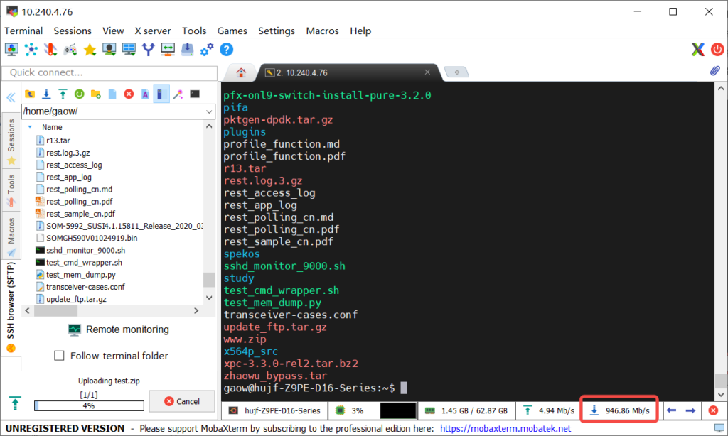
As can be seen from the screenshot, we transfer a 5GB file, with a transfer rate of 946.86Mb/S, which has basically reached the upper limit of the Gigabit network card.
3.4 Test of file transfer rate between wired terminal devices under different leaf modes
Upload a file from a computer connected to leaf3 to the server of leaf1 and check the transmission rate.
The traffic path of this test is as follows:
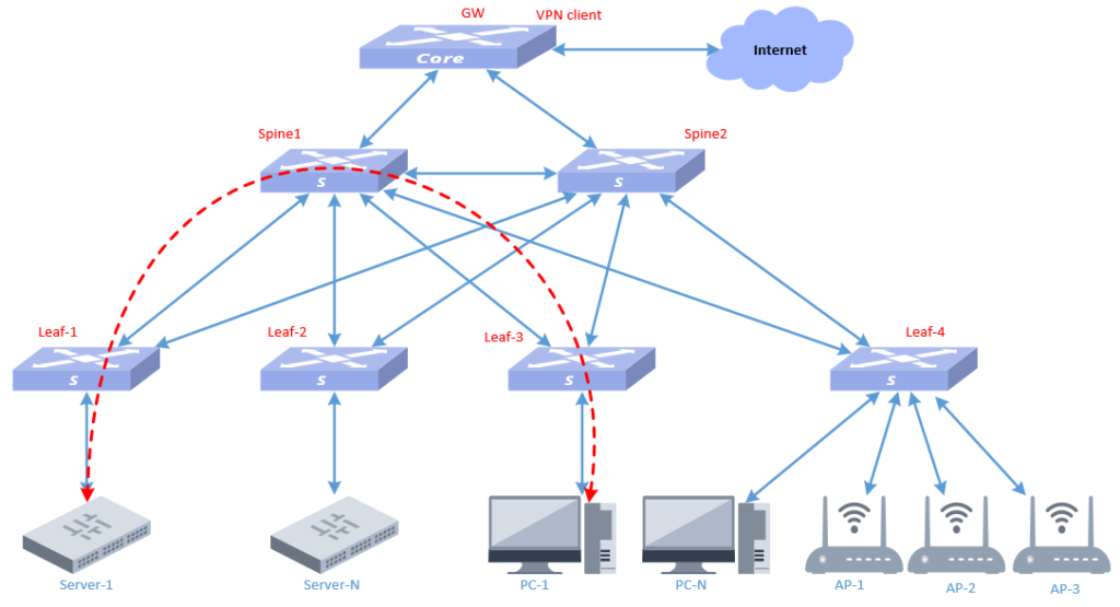
As shown in the figure above, the red dotted line indicates the traffic path.
This test uses the Xterm tool under the Windows system for transmission testing. The test screenshots are as follows:
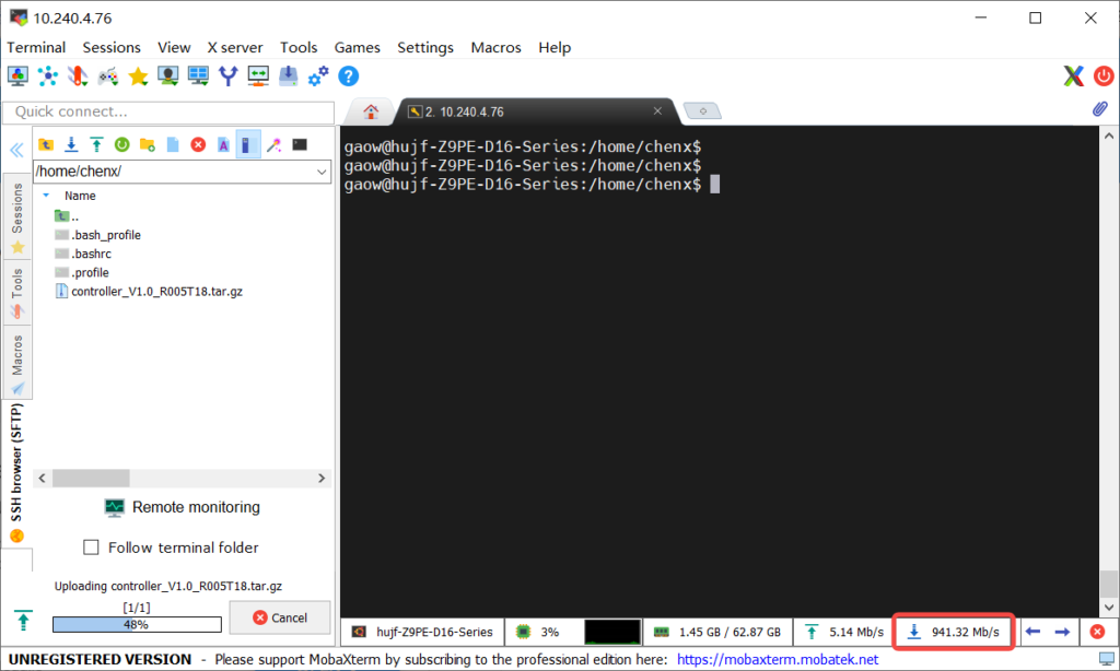
As can be seen from the screenshot, we transfer a 1.6GB file, and the transmission rate is 941.32Mb/S, which has basically reached the upper limit of the Gigabit network card.
The test results in sections 3.4 and 3.4 show that the intranet transmission rate can reach Gigabit speed, meeting the requirements of design planning. At the same time, it can be seen that the bottleneck of the intranet rate is the performance of the terminal network card. Regardless of whether the data is transmitted across leaves, there is no bottleneck in the entire intranet bandwidth.
3.5 Mobile phone download speed test
The test results are as follows:
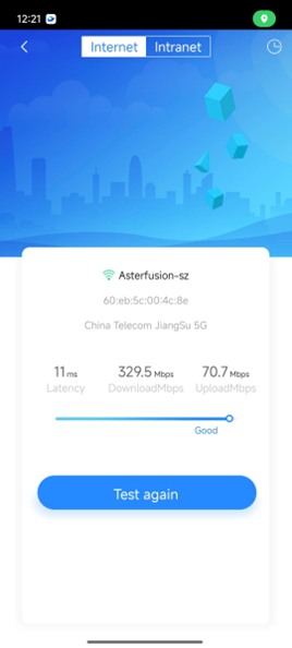
The test results show that the network speed is around 11 milliseconds, and the download and upload speeds are in line with expectations.
3.6 WI-FI stability test
Use your mobile phone to connect to WI-FI and move around the office area to check the signal stability. The results are as follows:
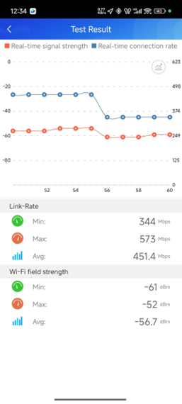
The test results show that whether you are stationary in one AP area or moving around the entire office area, the Wi-Fi signal is very stable and will automatically roam to the appropriate AP based on the signal strength.
4 Network Operation and Maintenance
The Asterfusion campus network has been built and the test results are in line with the construction expectations. Next, let’s introduce the network operation and maintenance work. The entire network is operated and managed by the controller.
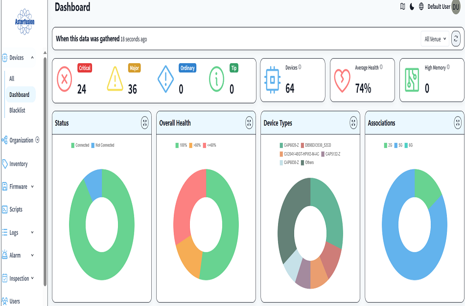
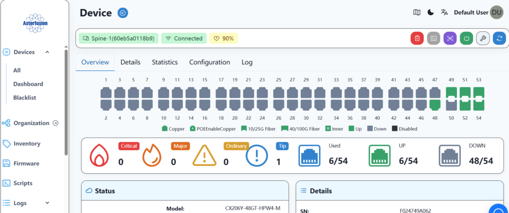
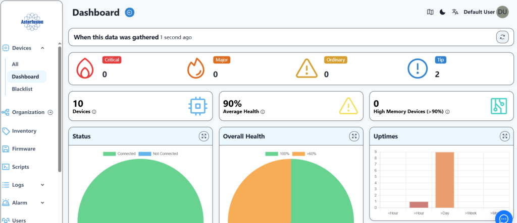
4.1 Check device status
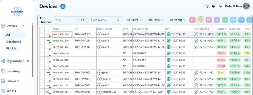
Here you can see the basic information of all devices, including memory and CPU usage, etc. At the same time, click on the mac information of each device to view the detailed information of each device separately.
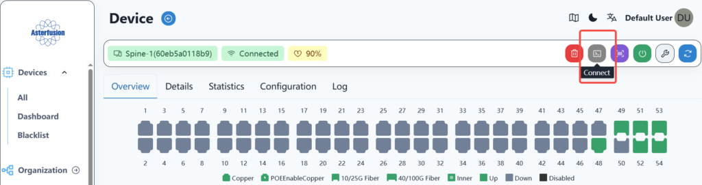
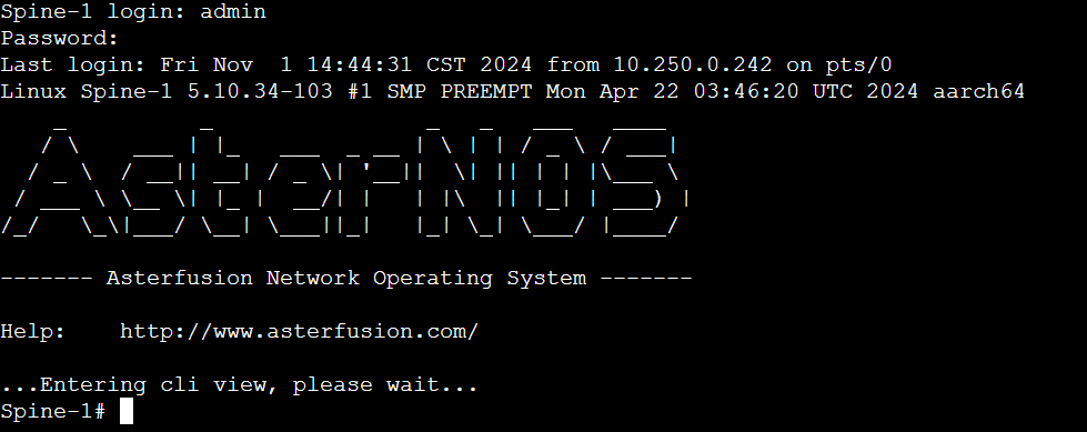
If you need to link to the device command line to view the underlying information, you can click the link button to enter:
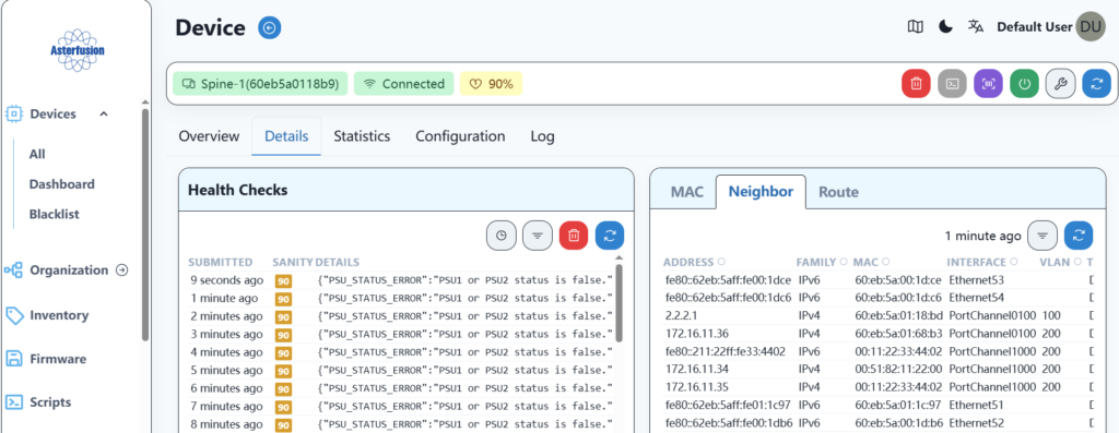
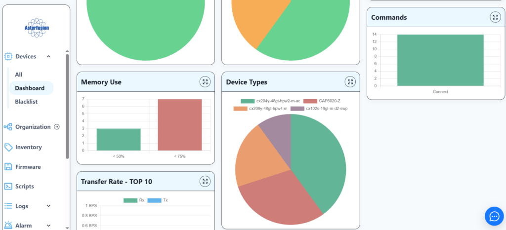
4.2 Network overall information presentation
Here you can view the information of the entire network equipment, including alarms, health status, etc.
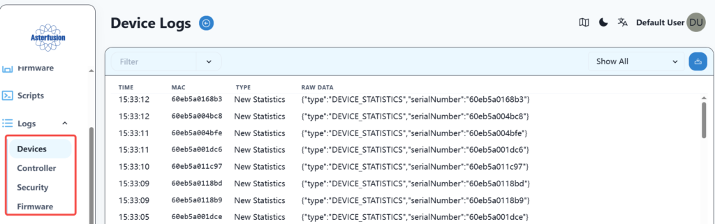
4.3 Log Information
Here you can view information such as device logs and controller logs.
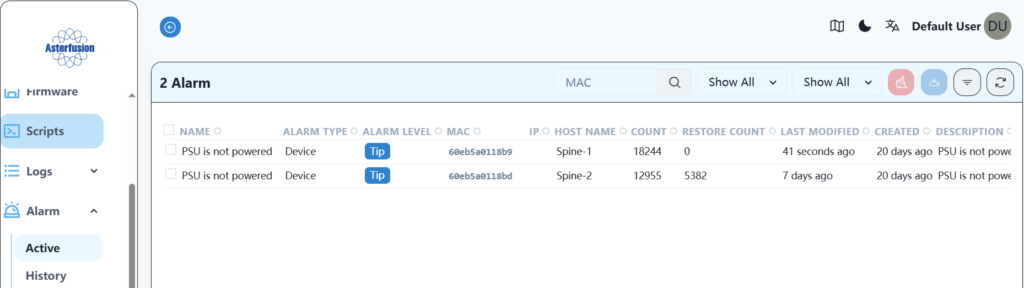
4.4 Alarm information
Here you can view alarm information, including current information and historical alarm information.
4.5 User Information
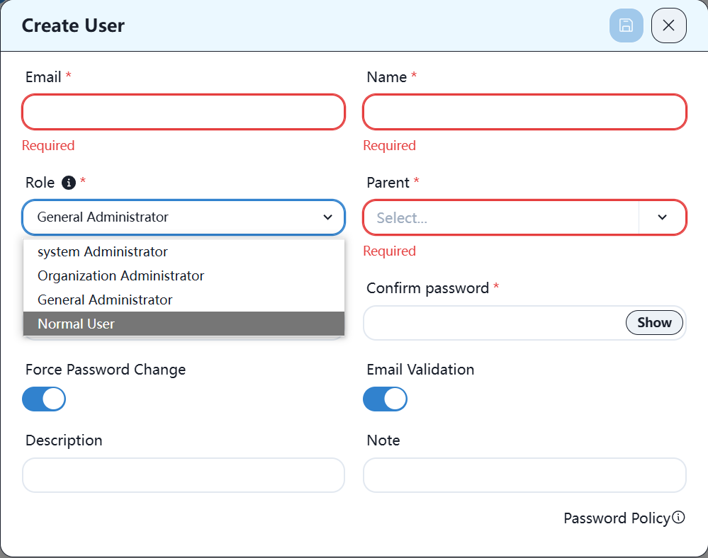
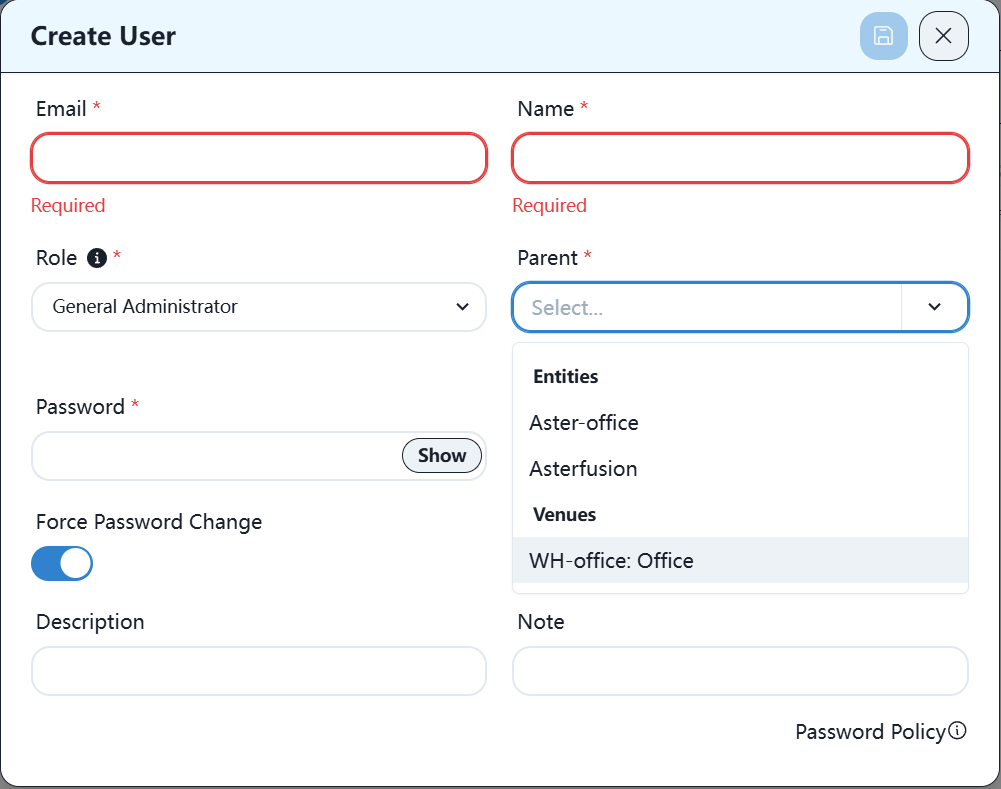
Here you can view, add and delete various users.
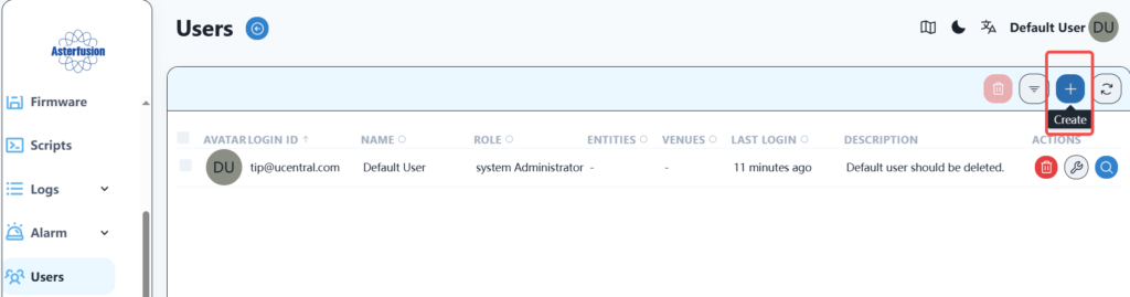
The roles include system administrator, organization administrator, general administrator and ordinary user. The system administrator has the highest authority, and the other roles can also select the corresponding organization and location.
4.6 User Information Analysis
The controller can be used to visually analyze the online status of terminal equipment in each R&D center, signal status and other information. Take BJ as an example, as follows:
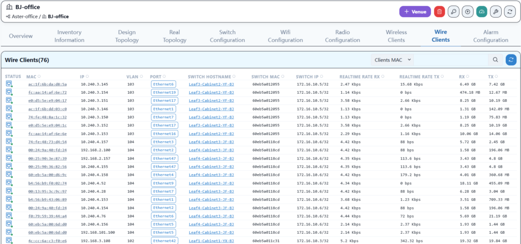
4.6.1 Wired terminal information
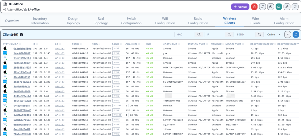
4.6.2 Wireless terminal information
4.7 Traffic Visualization
The network of each R&D center can view the traffic of the intranet. By accessing the IP address of DPU2 on the export device CX102S through the web client, you can view the specific statistical information of the network traffic.
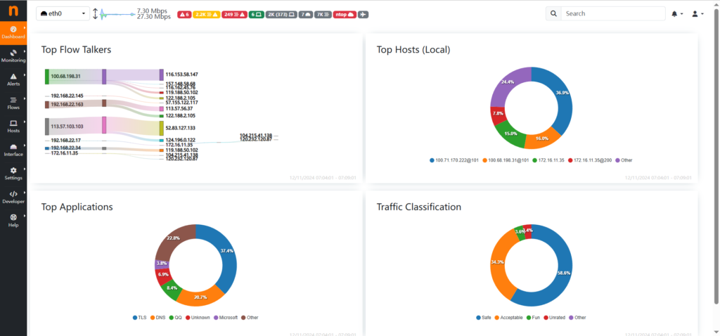
Taking WH office as an example, the overview information is as follows:
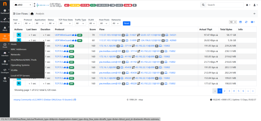
Active flow information is as follows:
The host information is as follows:
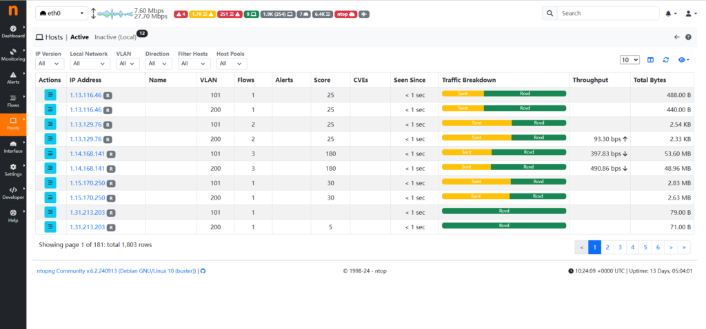
By viewing traffic statistics, you can promptly discover the access traffic of a specific host and, based on this information, restrict specific traffic by adding ACL rules at the egress.
5 Conclusion
Asterfusion campus network has been deployed. To summarize the entire deployment process, there are the following advantages:
- Deploying the entire network is simple and fast. After installing the controller and completing the comprehensive wiring, it only takes 30 minutes for a single R&D center to complete the deployment from equipment power on.
- Wireless networks support wireless roaming, and terminal devices can seamlessly switch between various APs without user perception, packet loss, or disconnection during the switching process.
- Full three-layer networking, distributed gateway, no broadcast messages within the network, effectively improving the utilization of internal network bandwidth.
- The internal network bandwidth of offices in various regions is high, and there is basically no bottleneck in network transmission performance.
- Business addition is convenient. If you need to add a wired business network segment, simply configure the business VLAN and gateway, and issue it to take effect.
- The overall operation status of the network can be visually presented, and the running status of devices and controllers, CPU and memory usage, running time, and other information can be viewed at any time.
- Easy operation and maintenance, able to view the real-time health status of equipment, and quickly locate problems and handle them in a timely manner based on logs and alarm information.
- Visualize the entire internal network traffic information, making it convenient for administrators to analyze the internet usage of each terminal.
Asterfusion CX-N & CX-M SONiC switches as the links below
CX-N series switches
CX-M series switches
If you have more technical questions, feel free to propose a ticket on our
https://help.cloudswit.ch/portal/en/signin